Welcome to the Onshape forum! Ask questions and join in the discussions about everything Onshape.
First time visiting? Here are some places to start:- Looking for a certain topic? Check out the categories filter or use Search (upper right).
- Need support? Ask a question to our Community Support category.
- Please submit support tickets for bugs but you can request improvements in the Product Feedback category.
- Be respectful, on topic and if you see a problem, Flag it.
If you would like to contact our Community Manager personally, feel free to send a private message or an email.
Options
Wiring Harness Struggles
 john_hauck
Member Posts: 54 PRO
john_hauck
Member Posts: 54 PRO
Greetings OnShapers!,
I created a wire harness (see pic below), but I feel a bit dirty about how I went about it.
I would love your thoughts on how this could be reworked better.
Here is the Document.

So first let me list the goals that I have for this task:

I now understand why Jon & Noa demonstrate the Wiring FeatureScript inside of a part studio where everything is created from scratch or brought in via "derived" and did not create lug connectors.
I believe there is room for improvement for wire harnesses in OnShape. For example:
- John Hauck
I created a wire harness (see pic below), but I feel a bit dirty about how I went about it.
I would love your thoughts on how this could be reworked better.
Here is the Document.
So first let me list the goals that I have for this task:
- To use the Wiring FeatureScript written by Jon Sorrells & Noa Flaherty as highlighted here: https://www.onshape.com/cad-blog/onshape-custom-feature-spotlight-wiring.
- To use wire lugs from another document or imported from STEP files.
- To have the harness adapt to changes in the top level assembly, by creating it in the context of the top-level assembly.
- To have the harness be an assembly containing the wire parts and with imported lug parts or assemblies.
- To be able to show the wire harness with lugs in its own assembly for creating a BOM and drawings of the harness.
- To be able to show the top-level assembly with the wire harness assembly hidden (including hiding the lugs).
- To create the wire parts in context of the top level assembly, they must be created in a Part Studio.
I call this the Wire Harness Part Studio.
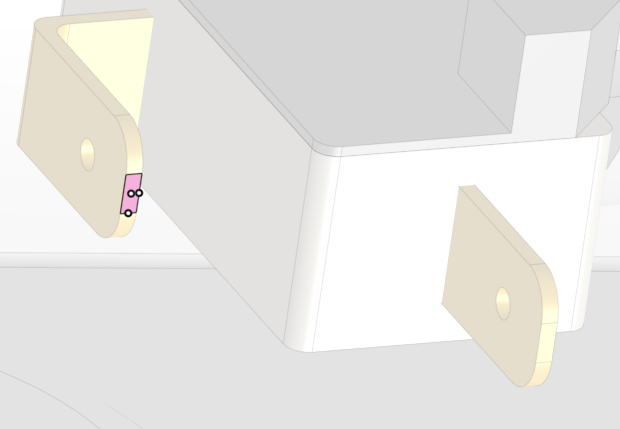
I decided to create a sketch on the face of every wire spade (male connector) in the assembly, and then create a point in the center of the spade for the Wiring FeatureScript (see picture below).
I then created all the needed wires, and added them to an Composite Part (and kept it "open"). - For adding lugs into the Wire Harness Part Studio I considered the following:
I could draw them from scratch in the Wire Harness Part Studio and duplicate them as needed. Drawing lugs is not a re-usable approach, so that is out. Furthermore, cloning and mating in a PartStudio using the Transform by Mate Connectors seems barbaric compared to the ease of mating parts in assemblies.
It is not possible to insert parts into a part studio like you can in assemblies, so that is out.
It is possible to "derive" parts from another part studio as a way of "inserting". Yet derived parts cannot be assemblies nor can they be composite parts, so that is out. Furthermore, it seems silly since nothing is being really "derived".
So I decided not to put lugs into the Wire Harness Part Studio. - The lugs then must go into an assembly.
They could be attached to the wire spades in the top level assembly or existing sub assemblies. This would however pollute those assemblies with lugs without wires which seems silly. Mainly, however, I really want the lugs and wires to be in their own wiring harness assembly.
Therefore, I decided to create an assembly called Wire Harness Assembly that contains the composite wire part and one lug mated to every wire end. I then added this wire harness assembly to the top level assembly. - However, I now have a Wire Harness Assembly and a Wire Harness Composite Part in the top level assembly. So the wires are essentially in the top level twice. I cannot remove the Wire Harness Composite Part because it is my only way of editing the wire harness in the context of the top level assembly. So, I simply make the composite part hidden (see picture below).
I now understand why Jon & Noa demonstrate the Wiring FeatureScript inside of a part studio where everything is created from scratch or brought in via "derived" and did not create lug connectors.
I believe there is room for improvement for wire harnesses in OnShape. For example:
- Inserting a composite part into a part studio might be useful (I think I would vote against this though).
- Better mating in part studios might help (I think I would vote against this though).
- Editing one sub assembly in the context of another sub assembly might be useful (I am starting to like this more and more).
- Have standard (and extensible) lugs (and other wiring parts) be part of the Wiring FeatureScript seems like a wonderful solution here. I'd like a lot of feedback before considering undertaking the task myself.
- John Hauck
Tagged:
0
Comments
I did exactly that a few days ago, and then trashed it because I did not want all the lugs in the main assembly.
There are my goals (specifically see #4-6):
- To use the Wiring FeatureScript written by Jon Sorrells & Noa Flaherty as highlighted here: https://www.onshape.com/cad-blog/onshape-custom-feature-spotlight-wiring.
- To use wire lugs from another document or imported from STEP files.
- To have the harness adapt to changes in the top level assembly, by creating it in the context of the top-level assembly.
- To have the harness be an assembly containing the wire parts and with imported lug parts or assemblies.
- To be able to show the wire harness with lugs in its own assembly for creating a BOM and drawings of the harness.
- To be able to show the top-level assembly with the wire harness assembly hidden (including hiding the lugs).
- JohnThank you for being persistent with me.
So I followed your instructions (with a few minor modifications) and here are my thoughts:
>> 7. Return to Main Assy.
Just to clarify I did not simply return to the main assembly, but I selected "Insert and go to Assembly", which is what I think you meant.
Also, instead of selecting all the wires for the insert, I first created a composite part of all the wires. I think this is in the spirit of your suggestion.
I then completed step 8 as you indicated and everything worked!
So now I have a part studio with the wires - and this still has a reference to the context of the main assembly at the time the wires were created. That is, the lugs are still in the main assembly because the context was created before step 8. I also have an assembly with the lugs and the wires. The main assembly includes the wire assembly.
Now I interact with this document as follows:
I updated the context of the wire part studio. This worked fine and the lugs are still visible. The reason they are visible is because that while the lugs were removed from the main assembly, they show up because they are now in the wire and lug assembly (which is in the main assembly). Very nice!
Now I changed the position of some of the parts that the lugs were mated to (in your step #1). The wires did not automatically follow the new lug locations (as expected). So I opened the wire part studio and selected the context. This context shows the original assembly and not the updated positions (as expected). I then selected "Update Context" and the new location of the sub assemblies are viewable in the ghosted image, and the wires did not move on some of the lugs but not on the others. It turns out that the reason it did not move on one was my fault. I did not properly constrain the point on the sketch that the wire was connected to. I fixed that, and poof it all moves as needed.
So now I went back to the main assembly, added two more lugs in new locations, then updated the context of the wire part studio, created two new sketches on those lugs, created the wire part between the two new sketches, and added the wire to the composite part of wires.
Now all I need to do is move those two new lugs into the wire and lug assembly. Hmmm. I'm stuck. Soooo close!
tl;dr Create a part studio in context, create sketches referencing the assembly geometry, create projected curves for the cable path. Make your mounts/harnesses from there. After changing the assembly, rmb > update context to see changes to the cables.
Twitter: @bradleysauln
So I created this simplified document Wireception.
- Create Cube part
- Create Hex part
- Create assembly Asm with 2 Hex and 2 Cube and fun mates
- Create part studio IC in context from Asm
- Create 2 sketches in IC on the 2 cubes in Asm
- Create one point on each sketch
- Create Wire from one sketch to the other
- Click "insert part into assembly" (the Wire)
- Select the Wire and both cubes and "move to new assembly" called Bsm
- Create version V1:

- So now we proceed.
- Change a mate in Asm to move the cube further away.
- Update the context of IC.
- Note that Bsm does not update.

- Create version V2
I think think the process of creating a "move to new assembly" of a part in context messes up OnShape in some way.Tab Asm: The Wire is in context of the assembly (arrow) - but nested inside Bsm - is that legitimate or a bug? I smell a problem!
Tab Bsm: The Wire is not in context of the assembly (no arrow) - hmmm.
Tab IC: The wire remembers the context of Asm (two arrows on each sketch).
The cubes in Bsm are not mated in any way either.
- John
Also, in your original assembly, you could delete the original hidden composite and set the composite in subassembly as Context primary instance' by right clicking. The context update as long as there is primary instance. I have made that change here https://cad.onshape.com/documents/7207f67811fdbdd4dda4887b/w/3f428e27d6b0350320dfd374/e/5c26bbcd16abd1747ac763e1
Essentially this is same as your simplified document created using Move to assembly once mate are added to make sure subassembly position is also correct.
Hope this helps.
Your first paragraph makes sense.
Your second paragraph is teaching me something I did not know about - "Set as primary instance". I took a screen shot of me about to perform that action (green rectangle). Can you confirm this is exactly what you are explaining here? To follow your directions further, I believe you mean I would also delete the Harness component part (red rectangle) too. Correct?
Thank you for teaching me something new.
- John
HWM-Water Ltd
In the end, I'm trying to something simlar to you, @owen_sparks.
But in the first stage, I am trying to make a pinout schematics. Unfortunately I will, right now, have to resort to import dxf:s of the connectors and make everything manually in Drawing.
I'm trying to delve deeper in to FS, but right now my programmingskills are basic, at most.
Cheeres,
P-O O
FS1 - I really think there is a strong case to be made that this should be done in an assembly. All the tools for importing and mating are in the context of an assembly. Deriving is just not the same. I really like it when I insert bolts from the standard content library, they are all set to be mated very nicely. An assembly is the place to assemble parts - including (in my mind) wire harness connectors. The down side is that OnShape does not support creating assemblies in context, so the goal of adding a wire harness as a sub assembly to a top level assembly is forcing us to use a Part Studio. Therefore, I reluctantly agree with your approach here.
Yet I wonder if OnShape is correct in not supporting sub assemblies in context. Here is another approach... what if we stop trying to add a wire harness as a sub assembly to a top level assembly. What if we use the top level assembly as a sub assembly in our new top-top level wire hardness assembly (TTLWHA). Now we can add wire connectors however we wish in this new TTLWHA. Now we can use the existing wire harness part generator, or something a bit nicer...
FS2 - I like the list of wire types and colors (sorry I type "American") as you describe. I also would like the ability to use mate connectors instead of sketches. The use of sketches makes things a bit barbaric. Mate connectors are awesome - because, well, that's their purpose. They can be re-aligned and moved, reoriented, and rotated. It's almost like they are made for this kind of work.
I'd also like to see the ability to specify a maximum wire bend radius, and the ability to insert and re-order the wire routing locations. And of course it would be super cool to have "collision detection" and force those wires to stop intersecting each other and the model itself. If we had that, we could specify one point for a bundle of wires to pass through, and collision detection would force them to clump together but not intersect each other.
That's all I've got for now.