Welcome to the Onshape forum! Ask questions and join in the discussions about everything Onshape.
First time visiting? Here are some places to start:- Looking for a certain topic? Check out the categories filter or use Search (upper right).
- Need support? Ask a question to our Community Support category.
- Please submit support tickets for bugs but you can request improvements in the Product Feedback category.
- Be respectful, on topic and if you see a problem, Flag it.
If you would like to contact our Community Manager personally, feel free to send a private message or an email.
Convenient tool / method for creating "tabs" (NOT sheet metal)
 tom_auger
Member Posts: 129 ✭✭
tom_auger
Member Posts: 129 ✭✭
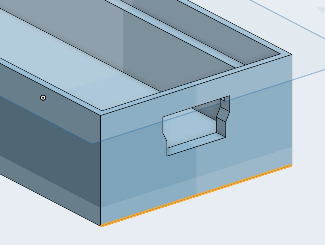
This part is meant to be screwed into a wall so I need some "wings" or "flaps" to extend outward (from the highlighted edge).
The naive way would be just to create a new drawing on the face, [u]se the bottom edge, and then extrude and thicken it. Then repeat that whole process for the opposite side, or mirror the resulting part. I'd love to do this without having to create a drawing just so I can extrude an edge that is already defined in some other geometry. Is there such another clever way of accomplishing this?
0
Best Answers
-
 bruce_williams
Member, Developers Posts: 842 EDU
@tom_auger
bruce_williams
Member, Developers Posts: 842 EDU
@tom_auger
Onshape lets you reuse sketch so you can have the tab shapes on your original sketch and Extrude Symmetric or Up to face with offset and the other end with Second end position.www.accuratepattern.com5 -
steve_shubin
Member Posts: 1,118 ✭✭✭✭
@tom_auger
YOU SAID — I'd love to do this without having to create a drawing just so I can extrude an edge that is already defined in some other geometry.
OK I’m assuming when you said without creating a drawing, that you actually meant - without creating a sketch.
You can create a flange by extruding an edge with thickness, using something called Thin-feature.

5
Answers
Onshape lets you reuse sketch so you can have the tab shapes on your original sketch and Extrude Symmetric or Up to face with offset and the other end with Second end position.
If you are making a solid, just stick to solid modeling techniques until they "can't" do what you need.
That being said:
select the face
create a sketch (shift+s)
draw a rectangle (g)
click one corner of the box
click the opposite edge
set a dim
extrude (new) -> set length
Mirror (Part) -> (Add)
Or you could sketch on the Front face of the part (the long face in my example) and draw two squares and make them equal length on each end.
There is absolutely nothing wrong with either approach. It seems like a lot of steps but, sketch/extrude is the bread and butter of solid modeling. It just becomes quicker with practice.
For solid modeling, only use surfaces if they shape is "funky"... or you need some sort of re-usable geometry to reference many features.
edit: forgot to attach the gif...
YOU SAID — I'd love to do this without having to create a drawing just so I can extrude an edge that is already defined in some other geometry.
OK I’m assuming when you said without creating a drawing, that you actually meant - without creating a sketch.
You can create a flange by extruding an edge with thickness, using something called Thin-feature.
https://cad.onshape.com/documents/24819ddab7dc83c810eb8246/w/927f8fded6e1be65852380a8/e/d4ef208f8075c2efd086c6be
YOU SAID — Is there such another clever way of accomplishing this ?
Here’s a way that’s more than twice as fast as using the Thin-feature extrude method
YOU ASKED — are you just creating a new sketch on the bottom face and then drawing a rectangle on it and extruding that?
ANSWER IS YES
YOU ALSO ASKED — If so - are the two sketches "linked' in any way such that if the dimensions of the first sketch change (say the width of the box), then the second sketch will also?
AGAIN, YES
Sketch 2 automatically added in constraints that linked it to the box (the extruded Sketch 1). Then as Sketch 2 was extruded, those flanges became one with the box as the extrusion defaulted to ADD.