Welcome to the Onshape forum! Ask questions and join in the discussions about everything Onshape.
First time visiting? Here are some places to start:- Looking for a certain topic? Check out the categories filter or use Search (upper right).
- Need support? Ask a question to our Community Support category.
- Please submit support tickets for bugs but you can request improvements in the Product Feedback category.
- Be respectful, on topic and if you see a problem, Flag it.
If you would like to contact our Community Manager personally, feel free to send a private message or an email.
Surface to solid
 nyholku
Member Posts: 60 PRO
Hi,
How do I turn a surface to solid?
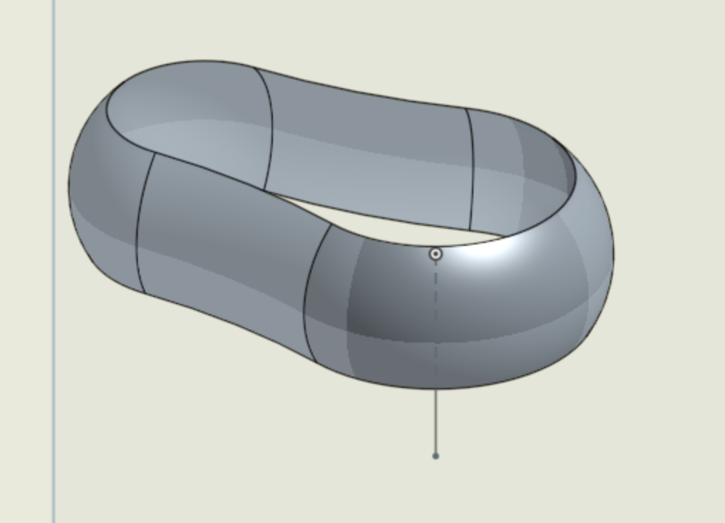
I've got a 'cylindrical' surface created by sweeping an open arc along a closed path . . . how do I close the open ends and create a solid?
I guess I can close the open arc and sweep that to create a solid and then boolean fill the centre but that feels like a hack ...

Tagged:
0
Best Answer
-
 viru
Member, Developers Posts: 619 ✭✭✭✭
Hi @kustaa_2 , Splitting of part method suggested by @jakeramsley was very easy and innovative. Apart from that there is one more workaround method for converting surface into solid. the steps are as below,
Step 1: Make a rectangle which is tangent to created surface.
Step 2: Sketch 2 extruded and created new part equal to height of surface 1. Step 3: Performed sweep remove operation by taking sketch 4 as sweep profile and edges of surface 1 as a sweep path .
Step 4: Delete surface 1 . Now only solid part 1 remain in window.
6
Answers
1. Create construction planes on the top and bottom surfaces. I used a plane point.
2. Thicken the entire surface inwards a small amount. Any small value should work.
3. Replace the top four faces with the top construction plane. Likewise with the bottom four faces with the bottom construction plane (this one will need to flip alignment as the top plane has a normal in the z-direction and the bottom faces have a normal in the negative z-direction).
4. Delete the interior faces.
The other option I was thinking was to make those same construction planes and then extrude a box that encompasses the surface up to those planes. From here, you can split the part you just created and have the interior.
1. Make a sketch of a rectangle that is larger than the desired part.
2. Do a two directional extrude, both up to the surfaces that you created.
3. Split the box with the surface you created. Either delete or hide the unwanted part.
Step 1: Make a rectangle which is tangent to created surface.
Step 2: Sketch 2 extruded and created new part equal to height of surface 1.
Step 4: Delete surface 1 . Now only solid part 1 remain in window.
Planar surfaces, as we have top and bottom of this example, are equivalent to the simplest form of extruded sketch, where the sketch entity is a straight line.
ON EDIT However, now that we have lofted surfaces, I see no reason why the method could not be bounded by these. And roll on other surface creation methods, including ruled surfaces, boundary surfaces and n-sided patches!
Step-1 Apply thicken feature internally. Hide the surface. You can also delete it by delete feature.
Step-2 Create datum planes by using three point option on both sides of the part for the three points as highlighted
Step-3 Create the sketch on one of the newly created plane by projecting all the outer edges
Step-4 Extrude the sketch up to bottom plane which is created by three point option.
Result will be solid body as shown below.
It seems to me that (in the more general case) your method does require that the resulting body would need to be checked for hidden cavities.
In some (but not all) cases these could be eliminated by increasing the dimension parameter of the thicken operation.
In recalcitrant cases, it might not be possible to sufficiently increase the thickness without making an invalid body. However, it might be possible to use "Delete Face" if all the faces of each hidden cavity can be picked.
I really just want a "fill this volume" command!
It seems that Thicken can't handle acute angles or something, because if I try to thicken the last tail piece it fails. I also tred Sketching a new object from the cross-section and revolving it, but then I get errors at the rounded end
Any ideas?
I made a volume encompassing it with an extrude then used the surface to split the solid. This only works because the edges of the surface are planar. I used a 3pt plane to create a sketch plane and then sketched a rectangle that is larger than the surface. I then extruded it so that the edges of the surface touch the face of my extrude. From here I used the split command to get a solid that has the boundary of the surface.