Welcome to the Onshape forum! Ask questions and join in the discussions about everything Onshape.
First time visiting? Here are some places to start:- Looking for a certain topic? Check out the categories filter or use Search (upper right).
- Need support? Ask a question to our Community Support category.
- Please submit support tickets for bugs but you can request improvements in the Product Feedback category.
- Be respectful, on topic and if you see a problem, Flag it.
If you would like to contact our Community Manager personally, feel free to send a private message or an email.
Sheet Metal - The missing step (for me!)
 peter_cuthbert
Member Posts: 56 ✭
Hi Folks
I am a new Onshape user having moved on from Alibre Atom. I was so pleased to see that you have sheet metal functions since I am in the middle of a sheet metal project. Having watched a couple of videos in adding flanges in which it looked so easy I thought I would have a go. So this is what I did, but the system would not let me select an edge:
1. Draw a rectangle for the door plate.
2. Thicken it up to 0.9mm, the size of the proposed metal.
3. Highlight the rectangle
4. Select Sheet Metal Model from the dropdown list
5. Select flange
6. Click on edge to be flanged
7. Edge does not highlight. Error message that sheet metal model 1 did not re-generate properly.
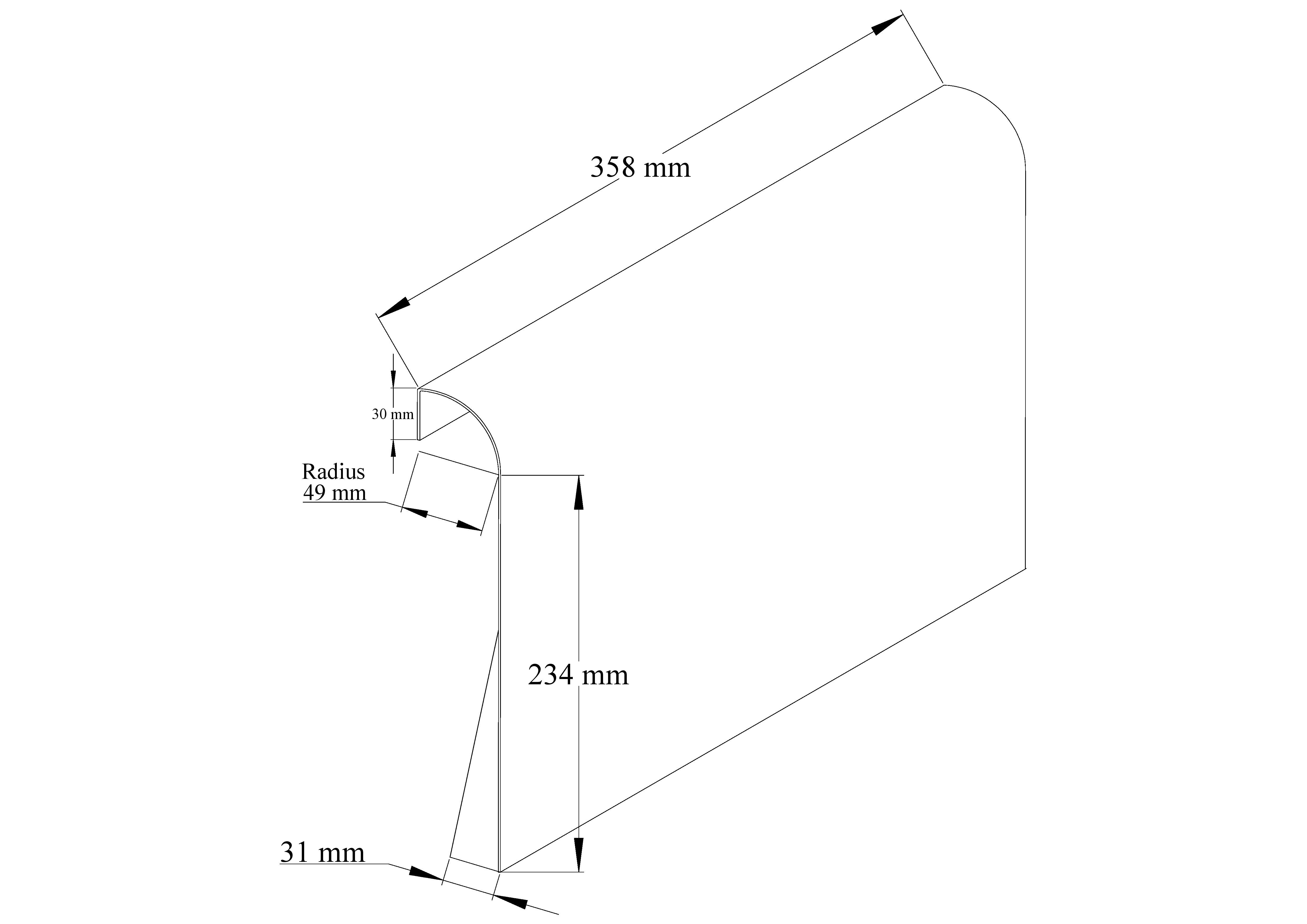
The part drawn as a 2D isometric should be shown in the picture below. The 'wings' at the lower sides of the door are hinge bar mounts. The vertical length of the triangle is 143mm which I see that I have not dimensioned. The door handle would be in the middle of the top on the curve.
Your advice would be most welcome.
Regards
Pete

0
Best Answers
-
 martin_kopplow
Member Posts: 1,182 PRO
@peter_cuthbertIt looks like the model you attempt calls for a flange added directly to a flange (or bend), which does not work. There just has to be a straight length between flanges. That makes abloute sense when it comes to manufacturability, anyway. It works, when you set the flange lenght to 1mm longer than the radius is.
0 -
 martin_kopplow
Member Posts: 1,182 PRO
Hi @peter_cuthbert , I just looked into your file, and I believe you are just making it more complicated than it is. With sheet metal, I'd always avoid sharp angled pointy parts and rather go for the beefy shapes. Keep in mind that while bending, the bending bench's jaw needs a certain width contact area, to hold the part down, which usually fails on pointy parts. It appears you are trying to attach the heavier sheet hinges to the thin sheet door: Wouldn't it make sense to make the flanges on the hinges, where the bend would be much sturdier, and leave the door as a straight sheet in that region? I can imagine this would make the whole assembly process much more stable. Also, you'd avoid the nick in the door.
0 -
 dirk_van_der_vaart
Member Posts: 561 ✭✭✭
I,m a bit late on this on.
In my opinion these simple construction,s are easy done in One single Part studio, all part,s related to each other and perfectly editable.
https://cad.onshape.com/documents/54d97e027be00435d8cb3131/w/c535d447bec8dd0e3d549898/e/5bba3faa5fb9f3c6eb629360
2 -
 peter_cuthbert
Member Posts: 56 ✭
Hi Dirk and GlenMany thanks for your contributions. Your versions of the boiler casing are so good. I will have to 'reverse engineer' your steps to see how it is done. Thanks too for the link. I will chase that up this morning.Sorry to hear that you have been under the weather with Covid Glen. Hope that you get on top of it soon. It certainly seems to knock some people for six so I am appreciative of your taking the trouble to respond to my questions. Indeed I am very grateful to everybody who contributes to these Forums as so many pieces of software seem impenetratable to the newbie. It also amazes me that folk are willing to contribute possibly at the end of a long working day. You are all 'Stars' in my book.Best wishesPete
0
Answers
Something like this (not to scale...):
https://cad.onshape.com/documents/d82feafe295a0de50d9f8fc9/w/f365a52750336cf7e75de52c/e/33560aee52a50b49f4353b48?renderMode=0&rightPanel=sheetMetalPanel&uiState=655bd8d641c7e17edcf6fb0c
@peter_cuthbert from reading your steps, I believe you may be trying to add a flange to a solid that is not actually a sheetmetal model, but instead a regular solid model. Please double check its sheetmetal first before adding flanges.
You'd want to work with the manufacturer to sort out what they need to reliably form that feature.
Couldn't help but notice all he transforms in your document. Not needed at all. This sample shows creating parts in place which is something OS does well so that updates to one part can propagate through others and hold relationships. Working way too hard by transforming parts.
I like Martin's version of the side brackets as well. Simplifies the main cover.
https://cad.onshape.com/documents/c34ea8221d89437c7bb321e1/w/c39f451e35b06203d6c38a9d/e/9b5bd8ee9d5dba4b73773e7d
I kinda thought that might be the case. It's something I used to run into when rushing to started to use in context edits.
Pretty much use the origin as my start reference now in stead of picking a part face. I can pick a reference part face once in the part studio to make my sketch.
For my own practice I did this as a cold smoker. Something I'm hoping to make next summer. This sample uses my current methods to avoid the parts out of place issue. There are 2 contexts for door open and closed. In busier designs, trying to move parts into place after the fact can get extremely messy with things still out of place.
While it's not a requirement to start initial part at the origin it can be very handy later.
Cheers
https://cad.onshape.com/documents/c34ea8221d89437c7bb321e1/w/c39f451e35b06203d6c38a9d/e/8133c5790597b23f515c1405
BTW If my initial post sounded a bit abrupt, it was not my intent. Having some ups and downs while I fight of a covid infection.
In my opinion these simple construction,s are easy done in One single Part studio, all part,s related to each other and perfectly editable.
https://cad.onshape.com/documents/54d97e027be00435d8cb3131/w/c535d447bec8dd0e3d549898/e/5bba3faa5fb9f3c6eb629360
For a newbie this is a realy good one to start with.
https://learn.onshape.com/courses/fundamentals-multi-part-part-studios
In 2016 I was in the same state as you are now so I understand your difficulties.
Take it easy and start with the basics of Onshape first, good luck