Welcome to the Onshape forum! Ask questions and join in the discussions about everything Onshape.

First time visiting? Here are some places to start:
  1. Looking for a certain topic? Check out the categories filter or use Search (upper right).
  2. Need support? Ask a question to our Community Support category.
  3. Please submit support tickets for bugs but you can request improvements in the Product Feedback category.
  4. Be respectful, on topic and if you see a problem, Flag it.

If you would like to contact our Community Manager personally, feel free to send a private message or an email.

Options

Sketch becomes unsolvable when doing anything, how can I fix?

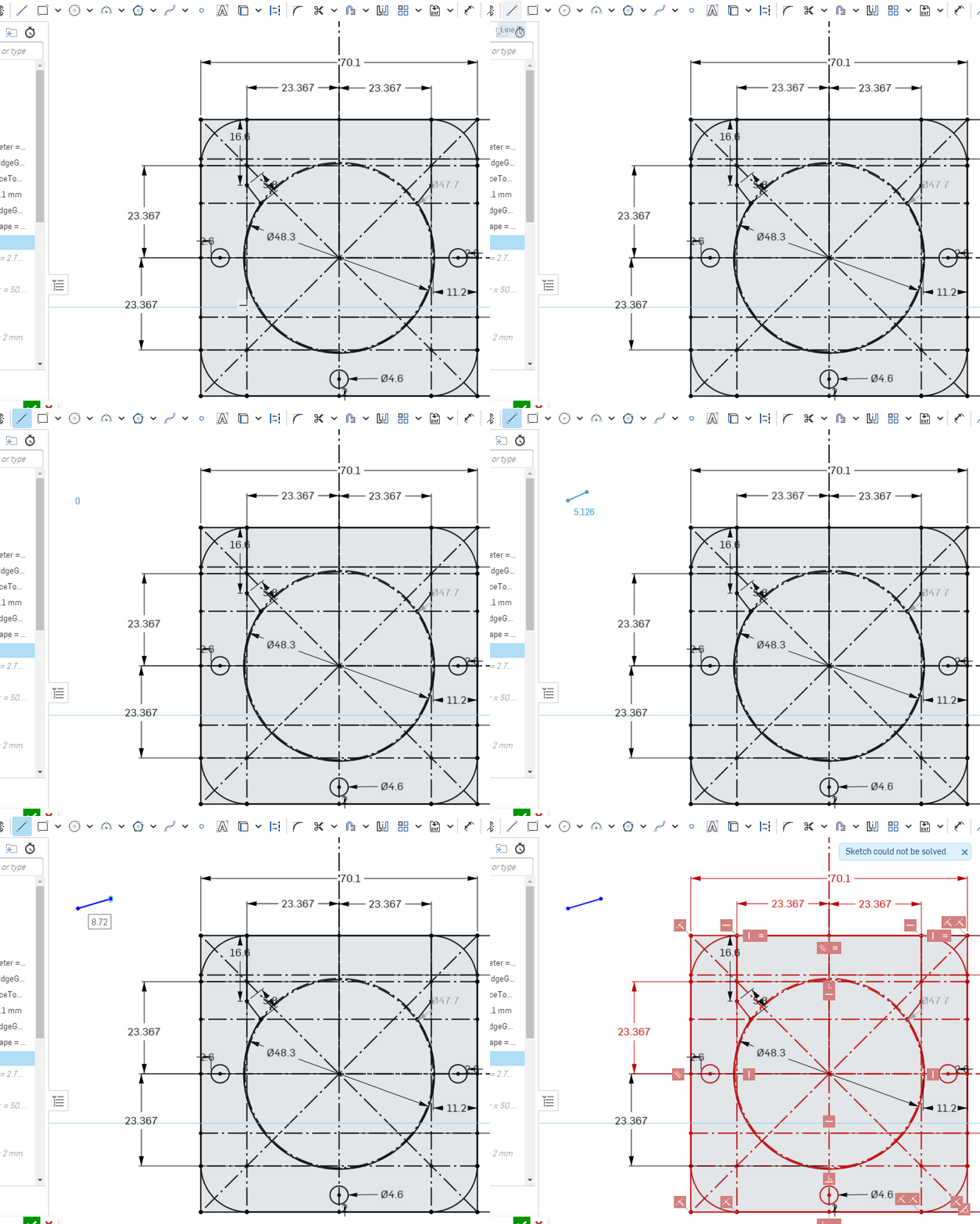
I have a sketch that is solved, but as soon as I do anything, even unrelated to any existing object, the sketch becomes unsolvable, saying "Sketch could not be solved". Even changing a dimension from 10mm to 10mm (ie, no change) causes almost every item to go red (only two dimensions stay black). I don't know what I can do to fix this. Can anyone help me troubleshoot it? See animated GIF below.

Link to drawing: https://cad.onshape.com/documents/0ba216c6d4b6634bdb89dd4c/w/b4428c3188ca0f28837b1c44/e/53e2a614f815fdfee5a465ee

Best Answer

  • Options
    NeilCookeNeilCooke Moderator, Onshape Employees Posts: 5,487
    Answer ✓
    There's probably a conflicting contraint in there, but your sketch is way too busy to find it. Good practice is to try to keep sketch entity count low and if you need more detail add it in a second sketch or feature. For example, do you need the corner fillets and all the construction lines here?
    Senior Director, Technical Services, EMEAI

Answers

  • Options
    NeilCookeNeilCooke Moderator, Onshape Employees Posts: 5,487
    Answer ✓
    There's probably a conflicting contraint in there, but your sketch is way too busy to find it. Good practice is to try to keep sketch entity count low and if you need more detail add it in a second sketch or feature. For example, do you need the corner fillets and all the construction lines here?
    Senior Director, Technical Services, EMEAI
  • Options
    jeremy_laidmanjeremy_laidman Member Posts: 8
    Thanks Neil. Yes, it is rather busy; I just figured I should put everything I know in the initial sketch so that if I want to adjust dimensions later, I can go to that sketch and change what I need. Although more recently I started using variables more, so this is now more of a bad habit than a strategy.

    I've deleted all of the curves around the edge and re-did them, and all of the broken relationships have gone. I don't know what caused it, but it's gone away now. Still seems like a bug, but I've worked around it.
  • Options
    eric_pestyeric_pesty Member Posts: 1,614 PRO
    Thanks Neil. Yes, it is rather busy; I just figured I should put everything I know in the initial sketch so that if I want to adjust dimensions later, I can go to that sketch and change what I need. Although more recently I started using variables more, so this is now more of a bad habit than a strategy.

    I've deleted all of the curves around the edge and re-did them, and all of the broken relationships have gone. I don't know what caused it, but it's gone away now. Still seems like a bug, but I've worked around it.
    There is an "upper limit" to how many constraints can be solved simultaneously in a single sketch that I have run into the past and I think this is what you were seeing. I like using layout sketches but this one is definitely too complex to be "useful" so breaking it up a bit is the way to go for sure. Makes it easier to work with as well.
  • Options
    Rhett_RobinsonRhett_Robinson Member Posts: 96 PRO
    @eric_pesty if this is the case, do you have a number for what this would be? I am curious if that has caused some errors I have seen in the past. I definitely try to break sketches up, but I can see how certain situations this could be required.
  • Options
    S1monS1mon Member Posts: 2,516 PRO
    edited February 12
    There are a bunch of issues with this sketch:
    1. Way too many centerlines which don't seem to be helping anything. It seems like this could easily be done with just a vertical and horizontal centerline.
    2. There are two centerlines which extend way way off into space, and two points on the opposite side. Did this start as something that was imported or copied? This makes hitting "F" for zoom full really annoying and may make the solver do weird things based on the overall extent of the sketch.
    3. There's a rounded square (70x70) and another one which is only slightly larger (70.1x70.1). As another engineer trying to understand your design intent, this was not immediately obvious. I would suggest perhaps separating these into two sketches with one sketch explicitly showing the clearance dimension.
    4. You have a bunch of cases where a dimension is repeated (2X 2.6, 2X 23.367). This is usually a sign that something could have been set to be equal or mirrored. 
    5. There's a 270 degree dimension. This seems really unnecessary unless there's some design intent to be able to modify this and make the shape into a parallelogram or something?
    6. There's a 20mm dimension to a centerline. It doesn't seem like this drives anything. What is its purpose?
    7. While I really like using equals relations in general to manage design intent (see #4), there are some cases where symmetric constraints would make a lot more sense and cause fewer things to need to be solved.
    8. The origin of the part is at the corner of the 70.1 square. This is really odd. Normally you would keep the origin at the center of a largely symmetric part. It will make mirroring features later easier.  
    I made a copy and refactored your Sketch 1. I kept the larger 70.1 square, but made that construction, since that doesn't seem to create real geometry later in the part. I did use one diagonal centerline, but I could have avoided that as well. I only used it to keep the rounded square equal on each side. Adding equals relations to edges of shapes which have fillets can make the sketch brittle (i.e. harder to fix/modify/work with later). In this case I just constrained the virtual sharp to the diagonal.


  • Options
    jeremy_laidmanjeremy_laidman Member Posts: 8
    There is an "upper limit" to how many constraints can be solved simultaneously in a single sketch that I have run into the past and I think this is what you were seeing. I like using layout sketches but this one is definitely too complex to be "useful" so breaking it up a bit is the way to go for sure. Makes it easier to work with as well.
    This may have something to do with it. However, if I were at the limit (not beyond it) with everything black, and all I did was change a dimension from 20mm to 20mm (no change, just over-typing what's there) I haven't added another constraint. Yet that's all I needed to do to trigger the fault. Perhaps by making changes I caused the solution engine to start its algorithm from a different point in the sketch, and process it in a different way, leading to it hitting a limit of sort.
  • Options
    jeremy_laidmanjeremy_laidman Member Posts: 8
    S1mon said:
    There are a bunch of issues with this sketch:
    Simon, some really helpful suggestions, thankyou. I'll take these on board in future models. In particular, I didn't know there was a symmetric constraint, so a fair number of the construction lines I add to sketches are to reproduce the same result.

    A few points that might explain some of the apparent anomalies:
    - The 70x70 square is not a square. There's a slight curve inward as you go from centre line toward the corners, so that when you get to the obviously rounded bit, the width has reduced by 1mm. This slight curve is required to fit inside the door lock housing, and it needs to be snug so that there's no wiggle room. The housing is slightly curved for aesthetic reasons. There are four points way out far from the part, which are the centres of these subtle curves.
    - The 270 degree dimension, and some of the other items way out into space are related to a circular pattern. I drew one corner and one edge, then replicated them around the centre, ending at 270 degrees.

    Thanks for making a fixed-up version (on a copy, not on the one linked in my question) for me to look at and learn from. As I mentioned, the edges need a slight curve, whereas those on your sketch are straight. I managed to do similar, essentially removing extra construction lines and circles, then removing the edges and corner curves (and the circular pattern), and doing them again, but simpler. On removing one of the edges, all of the broken constraints disappeared.

    Weirdly, when I open the sketch now (which I haven't changed since posting) the problem has gone away. I'm able to draw a link, change a dimension, etc, and the sketch is happy with all of the constraints.
  • Options
    NeilCookeNeilCooke Moderator, Onshape Employees Posts: 5,487
    There is no "upper limit" that I am aware of, but it is a system of simultaneous equations that need solving, so more detail = more math = more things that can be inferred incorrectly. In some scenarios, it is possible to have dimensions and constraints that agree with each other but don't flag as overconstrained, so simple changes cause chaos and may have something to do with the order in which the equations are solved. That's why we keep sketches simple.
    Senior Director, Technical Services, EMEAI
  • Options
    S1monS1mon Member Posts: 2,516 PRO
    edited February 13
    Interesting. I didn’t pick up on the subtle arcs. I’m confused because I didn’t see a 1mm width difference, but rather 0.1mm. From an ID and manufacturing level, 0.05 crown over that distance and size is within typical tolerances. If indeed you want a very subtle crown, I might add a driven radius dimension for reference just so the next person sees that those are arcs, not lines.

    Lots of tangent arcs can get fussy with the sketch solver, and arcs which are close to being lines are also tricky. It’s all doable, but too many dimensions and constraints can make things overly complicated and lead to it being twitchy.

    Sketch patterns are useful in certain situations, but this doesn’t seem like a good place to use them. You aren’t going to change the quantity or the angular spacing. 
  • Options
    jeremy_laidmanjeremy_laidman Member Posts: 8
    S1mon said:
    Interesting. I didn’t pick up on the subtle arcs. I’m confused because I didn’t see a 1mm width difference, but rather 0.1mm. From an ID and manufacturing level, 0.05 crown over that distance and size is within typical tolerances. If indeed you want a very subtle crown, I might add a driven radius dimension for reference just so the next person sees that those are arcs, not lines.

    Lots of tangent arcs can get fussy with the sketch solver, and arcs which are close to being lines are also tricky. It’s all doable, but too many dimensions and constraints can make things overly complicated and lead to it being twitchy.

    Sketch patterns are useful in certain situations, but this doesn’t seem like a good place to use them. You aren’t going to change the quantity or the angular spacing. 
    Yes, all good points. I've ended up not making them tangent arcs, and instead, just eyeballed that the corners and the sides are close to the same angle where they join. This is good enough for the practical purpose, and removes some constraints that are likely to be more computationally intensive.
  • Options
    rick_randallrick_randall Member Posts: 144 ✭✭✭
    Jeremy, All of the advice above is good - but I can assure you that Onshape is robust enough to handle any and all constraints needed for your sketch.
    Don't be afraid to use any constraint you need to fully define your work.  I have fully defined sketches far, far more complex, and had zero issues with using up to many resources.
    Like Neil said just clean up some conflicting constraints in the geometry( the errors are caused by two constraints fighting to do the same thing). With practice you'll learn to put only what is needed into your sketches ( leave out all redundant geometry). 
    S1mon's example sketch shows how to clean up your sketch to it's "simplest" form (always strive to accomplish this - in all your sketches).
    Good luck, keep at it

  • Options
    jeremy_laidmanjeremy_laidman Member Posts: 8
    Like Neil said just clean up some conflicting constraints in the geometry( the errors are caused by two constraints fighting to do the same thing). With practice you'll learn to put only what is needed into your sketches ( leave out all redundant geometry). 
    Thanks Rick. The puzzling thing to me is that the constraints were OK until I did an action that had no bearing on the constraints, and then they were in conflict. If I have a dimension that's set to 20mm and there are no conflicts, then I change that dimension to 20mm, and there are now conflicts, then I can't understand what could be wrong with the sketch after that change that wasn't showing as a problem before that change.

    But I take your general point that I should think ahead a bit, and put in constraints in a logical way, so that I don't end up with conflicts. Until now, I've just been hacking away, and dealing with conflicts as they arise, by thinking about the last operation I did. It's a quick-and-dirty strategy but it's worked for the simple projects I've done, with this one exception.
Sign In or Register to comment.