Welcome to the Onshape forum! Ask questions and join in the discussions about everything Onshape.
First time visiting? Here are some places to start:- Looking for a certain topic? Check out the categories filter or use Search (upper right).
- Need support? Ask a question to our Community Support category.
- Please submit support tickets for bugs but you can request improvements in the Product Feedback category.
- Be respectful, on topic and if you see a problem, Flag it.
If you would like to contact our Community Manager personally, feel free to send a private message or an email.
Best Of
Improvements to Onshape - November 18th, 2020
It's November! We are near the end of 2020, but we are not slowing down. This release includes a number of frequently requested features including markup! Lets take a look.

CAD IMPROVEMENTS
ABILITY TO APPLY MARKUP TO COMMENTS
Markup is now available in the Comments section of Onshape.EXPLODE LINE FORMAT IN DRAWINGS
Control explode line weight and color in Drawing properties > Views > All views.SECTION VIEW OPTIONS
When you add a Section view to a section view, you can choose whether to cut the base geometry or cut the already sectioned geometry with a toggle.
MOBILE IMPROVEMENTS
IOS INSERT IMAGES FROM MOBILE DEVICE
Now you can import local images or take an image from your camera for import into Onshape on an iOS mobile device.ENTERPRISE IMPROVEMENTS
COMPANY SETTINGS
Enterprise administrators can see how many full and light subscriptions have been purchased as well as how many are in use. Go to Enterprise settings > Users and they are listed at the top.

The number and type of subscriptions purchased also show under My account > Subscription.

Please take a moment to try out these new features and improvements and leave your comments below. For a detailed list of all the changes in this update, please see the changelog.
Remember: The updates listed here are now live for all users when creating new Documents and over the next few days these features will also be available in Documents created before the date of this update.
Remember: The updates listed here are now live for all users when creating new Documents and over the next few days these features will also be available in Documents created before the date of this update.

Re: Improvements to Onshape - November 18th, 2020
We will make use of all of these (probably Markups most of all). Thank you.
 Theo_R
5
Re: How to make a hidden object not show up in Drawings?
@LKRENZLER We show all parts in drawing views whether they are hidden or not in the assembly. This is by design and prevents issues with collaborative editing where drawing views are being un-knowingly affected from users hiding/showing parts in assemblies. If you want something other than "Show all" in drawing views, you can create a display state in the assembly and then reference that display state from the drawing views.

Re: Miura Fold in Onshape
I made a quick working version to try out a couple things. I think you'll find success with these tips:
Good luck!
- use surface bodies at first to get the mates correct. When using Mate Connectors for mates, Onshape doesn't care about your rounded edges, but they may make it difficult to select the right edges for the Mate Connectors. Surfaces will make the early work of figuring out the Mates much simpler
- use the least-restrictive Mate types possible. For my sub assembly (4 panels, like yours) I used 3 Revolute mates and 1 Ball Mate.
- When you assemble the sub assemblies together, continue to try to use the least-restrictive mates where possible....
- When placing new sub assemblies into your Main Assembly - use the Group to (temporarily) freeze your sub assemblies so they can't fold while you're trying to apply mates to the existing parts. Remember to delete the Group before you add all the mates, or try to drag your assembly to check the motion. You can also suppress/unsupress a Group on your first sub assembly while mating - this will effectively freeze all motion while you apply mates.
Good luck!

Re: Miura Fold in Onshape
I saw this fold years ago and it stuck with me, but I haven't come up with a search term to find it since so thanks! Pin-slot isn't what you want. it's for things like this: 
I used a combination of revolute and cylindrical mates to get it working. When i used all revolute it would become overconstrained, which I assume has something to do with Onshape's internal tolerance since it should work in a perfectly precise world. Using some cylindrical constraints loosens it up a bit.

I used a combination of revolute and cylindrical mates to get it working. When i used all revolute it would become overconstrained, which I assume has something to do with Onshape's internal tolerance since it should work in a perfectly precise world. Using some cylindrical constraints loosens it up a bit.

New Video: branches and merges without the guesswork
Hi everyone, I've been wanting to make this video for a while since I've seen so much confusion (including my own) around what branching and merging actually does. After playing around and experimenting with it a lot, I've finally come up with my own way of thinking about it that really makes sense to me, and I hope it can clear it up for anyone who is as confused as I was about it starting out. Let me know what you think!
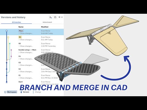 https://youtu.be/XjdaRcD0faQ
https://youtu.be/XjdaRcD0faQRe: Show History in Edu Version?
@timothy_jump
Copied documents do not copy history. The only way that you can tell if it was a copied document is if the version called 'Start' is empty or not.
You should be able to view changes that the student made if you go `> show changes` below the 'Main' workspace.
Copied documents do not copy history. The only way that you can tell if it was a copied document is if the version called 'Start' is empty or not.
You should be able to view changes that the student made if you go `> show changes` below the 'Main' workspace.

Re: How do you curve the point on a cone? I don't like how sharp/pointed the
Hey Jasmin Tyler. Her is my method to accomplish the result that I understand you desire. Let's see your attempt. - Scotty

Re: Is there a way to make a gravity effected ball in the assembly or part studio.
I would be warry of a Tangent sphere to the track.
Instead I would try adding a track guide that the marble follows with a mate connector or some reference point
If you want the marble to appear to rotate, that will be an artistic challenge. For that add your marble to a sub assembly and have a spearate relation making the marble spin in it's assembly, while a mate connector in the assembly is mated to your track
That make sense?
Sorry i can't throw an example your way i'm not by a computer for the next few days

Re: Onshape, we are here for you!
Nothing gets past you lot!
Over the weekend an incorrect branch of our website was pushed to production. We are about to finish a re-brand and are excited about getting fully integrated into the PTC family. Please stay tuned while we fine tune our website UX. Please keep in mind, we are still the same Onshape, just a bit greener.
Over the weekend an incorrect branch of our website was pushed to production. We are about to finish a re-brand and are excited about getting fully integrated into the PTC family. Please stay tuned while we fine tune our website UX. Please keep in mind, we are still the same Onshape, just a bit greener.
 NeilCooke
10