Welcome to the Onshape forum! Ask questions and join in the discussions about everything Onshape.
First time visiting? Here are some places to start:- Looking for a certain topic? Check out the categories filter or use Search (upper right).
- Need support? Ask a question to our Community Support category.
- Please submit support tickets for bugs but you can request improvements in the Product Feedback category.
- Be respectful, on topic and if you see a problem, Flag it.
If you would like to contact our Community Manager personally, feel free to send a private message or an email.
Best Of
Re: Configuration Titles
To get around the current headers limitation this is my preferred workflow.
(1) Set up standard partstudio variables.
(2) Use those variables to control sketches or features.
(3) Use configurations to control the values in the variables.
That way to you get sensible names in the headers, ie the variable names you set.
Hope that helps.
Owen S.
(1) Set up standard partstudio variables.
(2) Use those variables to control sketches or features.
(3) Use configurations to control the values in the variables.
That way to you get sensible names in the headers, ie the variable names you set.
Hope that helps.
Owen S.

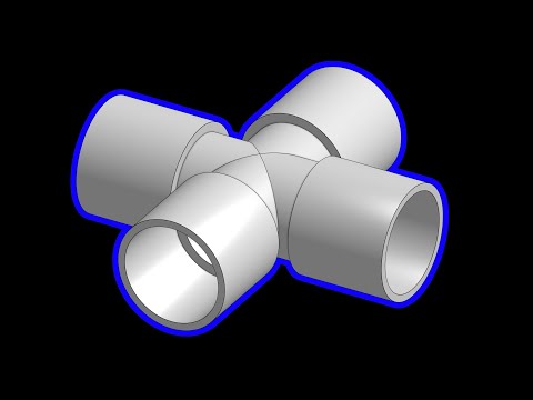
And now, for something a bit silly... (How It's CADded Pilot/Test Episode - PVC Fitting)
So, I had a silly idea and decided to make this haha. It's a crossover in the styles of CGMatter (super fast Blender tutorials) and How It's Made (TV show documenting manufacturing of various goods). Essentially, the idea is to make a quick, funny CAD tutorial that's fun to watch even you aren't a mechanical engineer/CAD user, but if you are one, there are little workflow tricks that might help you out. The narration and music are inspired by the narration and theme song of How It's Made.
This is a pilot/test episode, so things may be a bit rough around the edges. Please let me know any feedback you have!
This is a pilot/test episode, so things may be a bit rough around the edges. Please let me know any feedback you have!
 https://youtu.be/-5sQV18yJzs
 alnis
alnis
9
Re: David Van Der Wee
Unfortunately you cannot link the child views if one of the views is broken. (Yet)
You will need to "eye ball" this for now.
Let's hope we see this fixed soon. There should be improvement requests floating out there, get your name on that list to help them prioritize updating this.
The button is here:

More info here:
https://cad.onshape.com/help/Content/drawings-views.htm?Highlight=break
You will need to "eye ball" this for now.
Let's hope we see this fixed soon. There should be improvement requests floating out there, get your name on that list to help them prioritize updating this.
The button is here:
More info here:
https://cad.onshape.com/help/Content/drawings-views.htm?Highlight=break

Re: Wrap a sketch (or extrusion) around a cylinder
@duncan_thomas let me know if this is helpful.
I would create a cylinder with a plane tangent to the face.
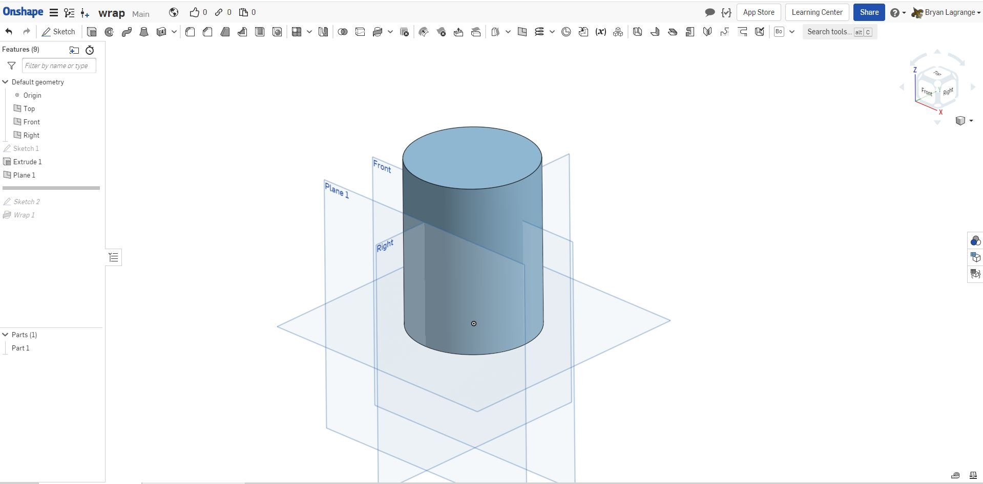
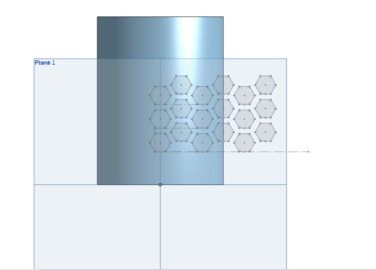
On the tangent plane create a sketch of the hex grid. I used the polygon command and then did some patterns to make a grid.
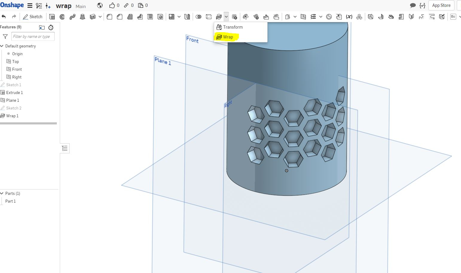
Then use the wrap command to extrude, cut, make a surface.

here is the link to the model: https://cad.onshape.com/documents/07d746e9644e895931f2fcfc/w/8ca25cd353d0c816939a2547/e/1b5d82e8f3b351b04adbb22c
I would create a cylinder with a plane tangent to the face.
On the tangent plane create a sketch of the hex grid. I used the polygon command and then did some patterns to make a grid.
Then use the wrap command to extrude, cut, make a surface.
here is the link to the model: https://cad.onshape.com/documents/07d746e9644e895931f2fcfc/w/8ca25cd353d0c816939a2547/e/1b5d82e8f3b351b04adbb22c

Very Configurable Espresso Machine (Just Showing Off Again)
https://cad.onshape.com/documents/4833676df7d2a808ac4b52b7/w/1779c4496f69618947b539b5/e/75f2654cbbb785c3812333d2?configuration=BPG%3Dtrue%3BList_SkU4QbgzZJU3Zv%3DCopy_of_4_0_2005_Today__Stradivari_design%3BList_ps7sMPFLqllg22%3DChrome%3BRemove_Bottom_Cover%3Dtrue%3BThreads%3Dtrue
Most relevant of 9 videos:
https://youtu.be/c5pp2y50D_g
Playlist of 9 videos:
https://www.youtube.com/playlist?list=PLPX9KWMNFMwNk_aBK7plrFBF1VJx0OMVw


Most relevant of 9 videos:
https://youtu.be/c5pp2y50D_g
Playlist of 9 videos:
https://www.youtube.com/playlist?list=PLPX9KWMNFMwNk_aBK7plrFBF1VJx0OMVw

Re: Multiple Part Studios or Multiple Parts Per Studio?
It depends on what you are designing. If the parts are related (dimensions depend on each other, shapes depend on each other, tightly integrated, etc.), it's best to put them in one part studio so that they can be modified together and you can visualize how they will fit together (e.g. parts of a casing with snap hooks holding them together, a mechanical linkage with custom parts, frame made of beams, laser cut panels, etc.).
However, if the parts are not related or are defined by outside specifications rather than the specific model/project you are working on (such as standard parts across projects, COTS parts, custom fasteners or other reusable parts, etc.), it's best to put them into individual part studios. This will make them easier to work with and will improve regeneration times since a modification to a part will only require the regeneration of that single part, avoiding regenerating a bunch of other parts.
I find that I often model tons of parts at a time in one part studio during the roughing out stage and make more reusable, "atomic" part studios with low part counts (or just single parts) to make components of the design more reusable later on. The short summary is:
- If the parts are interrelated and are unique to the project, a single part studio is most appropriate
- If the parts are interrelated but will be reused for other projects (e.g. standard-sized gusset plates to hold beams together), it may be better to separate them into different part studios for increased performance and ease of reuse, but it depends on the case
- If the parts are not interrelated, separate part studios should be used
Hope this helps! I can make some quick example models if you'd like")
However, if the parts are not related or are defined by outside specifications rather than the specific model/project you are working on (such as standard parts across projects, COTS parts, custom fasteners or other reusable parts, etc.), it's best to put them into individual part studios. This will make them easier to work with and will improve regeneration times since a modification to a part will only require the regeneration of that single part, avoiding regenerating a bunch of other parts.
I find that I often model tons of parts at a time in one part studio during the roughing out stage and make more reusable, "atomic" part studios with low part counts (or just single parts) to make components of the design more reusable later on. The short summary is:
- If the parts are interrelated and are unique to the project, a single part studio is most appropriate
- If the parts are interrelated but will be reused for other projects (e.g. standard-sized gusset plates to hold beams together), it may be better to separate them into different part studios for increased performance and ease of reuse, but it depends on the case
- If the parts are not interrelated, separate part studios should be used
Hope this helps! I can make some quick example models if you'd like
alnis
2
Re: HELP! How do I trim a surface with a sketch?
mitchel_palmer said:Onshape requires a "work around" of multiple steps

Re: Rollback Bar User Experiance
I would also like to have hotkey to 'roll to end' to avoid misunderstanding why things are missing from assembly.. I will write few IRs on this later.
BTW in Alibre there is indicator in assembly mode which tells the user that some particular part is not completely build in part design. This is very handy since you can easily forget to 'roll to end' and then assemblies brake or there are missing parts.
@philip_thomas
Can I make an IR for Onshape employees being able to write IRs on behalf of pro users on demand - so that it would have same value as written by user? It kind of hits on my eyes/ear every time I see Ons employee asking for paying customers to report something again 'formally'.
I understand the idea but I think the actual mechanism needs some advanced tools to value also customer efforts to write in your official forum.
 3dcad
3dcad
6
Re: Feature UI: 2 booleans on a row?
We currently don't support DISPLAY_SHORT for stacking checkboxes horizontally. Our thinking is that checkbox options are easier to read when stacked vertically, especially when the text can be translated to a language that causes the labels to become longer and possibly truncated.
 kori
kori
5
Re: How do I add threads to a hole.
Hi all.
This is a popular topic and often forms "one of the first things I must try in CAD".
In all honesty the initial thought you should ask yourself is "do I need to model this thread?"
This is because they are needy little sods from a performance point of view. They can be time consuming to model but more importantly they can contain more work for the CAD SW to perform every time it rebuilds than all of your other parts combined. (Just think how many faces you have if your assembly has 50 bolts in it, and 50 tapped holes for them to fit into.)
From an engineering point of view we want a drawing with a call out to the thread type, which the "hole feature" covers well. Then our CNC machine has a pilot hole only on the model, the last thing it wants is modeled threads.
If you really really need threads (say for a rendering of finished product, or for 3d printing) then a good tip is to build them but then suppress the feature when you're working on the rest of the model.
Even in 3D printing placing a captive metal nut in the model (and then pausing mid print to drop it in) is usually a better option.
Just my 2p's worth
Cheers,
Owen S.