Welcome to the Onshape forum! Ask questions and join in the discussions about everything Onshape.
First time visiting? Here are some places to start:- Looking for a certain topic? Check out the categories filter or use Search (upper right).
- Need support? Ask a question to our Community Support category.
- Please submit support tickets for bugs but you can request improvements in the Product Feedback category.
- Be respectful, on topic and if you see a problem, Flag it.
If you would like to contact our Community Manager personally, feel free to send a private message or an email.
Best Of
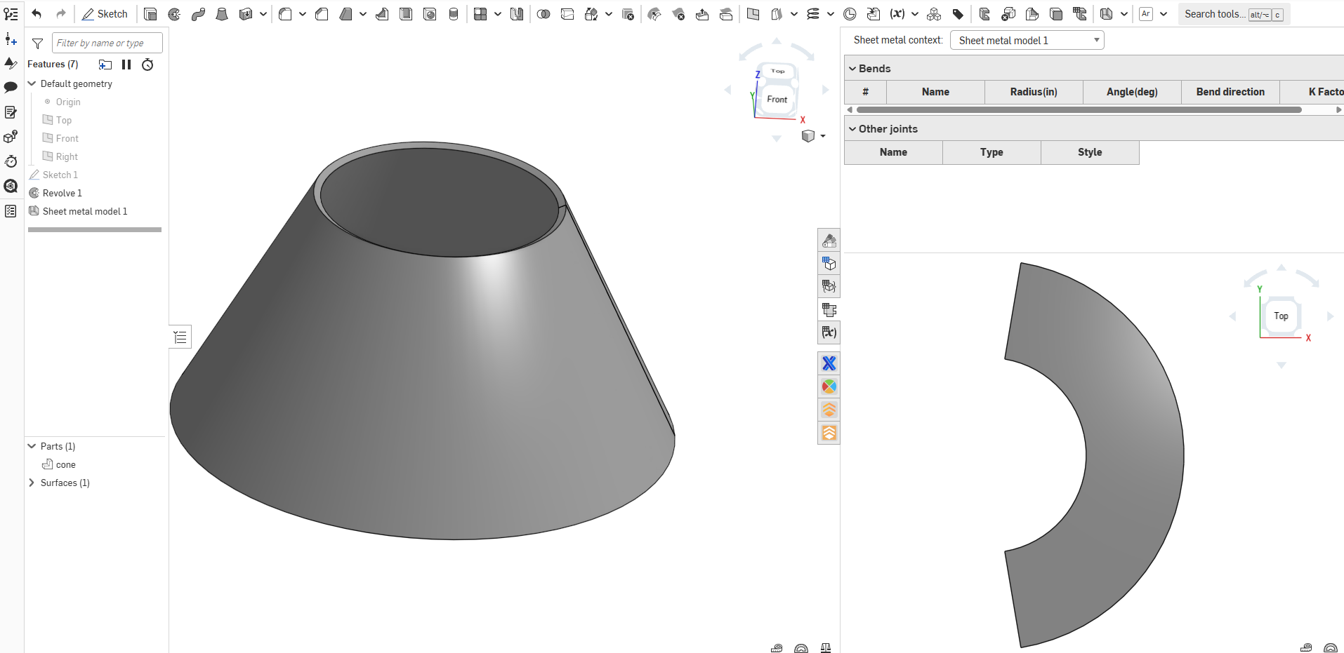
Re: Sheet Metal Model from apparently continuous surface
Never thought of making a sheet metal cone this way. Thank you @lana

Re: Gun checkering texture
Woah. What in the tarnation? I need to study up on how you used that as a linear feature pattern. The brain is not braining on that one yet. Thanks for whipping that up. I'll see if I can make it work on my part.
 MDesign
1
Re: etching
Just insert a flat pattern as a view in your drawing. I usually use an empty sheet for this. Then export the drawing as DXF/DWG.