Welcome to the Onshape forum! Ask questions and join in the discussions about everything Onshape.
First time visiting? Here are some places to start:- Looking for a certain topic? Check out the categories filter or use Search (upper right).
- Need support? Ask a question to our Community Support category.
- Please submit support tickets for bugs but you can request improvements in the Product Feedback category.
- Be respectful, on topic and if you see a problem, Flag it.
If you would like to contact our Community Manager personally, feel free to send a private message or an email.
Best Of
Re: Named render modes
Doesn't quite solve your problem but you can have two browser tabs open of the same thing, one setup for each of your preferred modes.
You are still going to have to set that up with every "session" (and every part studio or assembly) but it will allow you to switch back and forth (or even have both on screen at the same time.

Re: Going crazy with onshape moving my objects.

Re: Going crazy with onshape moving my objects.
I have this after i strictly constrain EVERYTHING, and work on something for 5 hours to find out that it has decided to shifted everything.. slightly and randomly for no reason so i have to delete everything and restart.

Re: how do we smooth out (blend?) the end of custom threads?
#2 is the standard way that real injection molded closures are done. They use a rotating mill bit to make the features in the tool.
 S1mon
S1mon

Re: Hole Feature - no more blind in last?? and no more custom hole sizes
How do you create a Clearance and Tapped Hole whit the new update?
Hole Feature - no more blind in last?? and no more custom hole sizes
Surfacing with the new stuff
You gotta watch this:
And then use these:Greg's Curve and Surface eval tools are here:
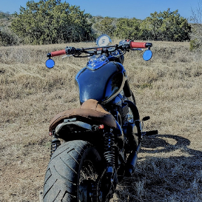
This is my 3rd generation design for this part, it's a 2016 BMW R9T (8 years old):

This is the most primary surface in my design, Greg talked about these in his video and getting these correct is important. Most organic designs will have primary surfaces:

This is actually a good single span surface patch with degree 3 & 4 to create it's shape.
This is how my old design was created using a simple loft through 3 curves:

Turns out this surface is terrible:

Instead of using a 3 curved loft to create my primary surface, I switched to a 4 sided boundary surface:

This new boundary surface is off by .309 mm using a 4th order target and that doesn't matter for the design. The red dot in the image above shows maximum deviation between the old & new shapes.
This middle curve defines where the part matches the seat:

I can't remove it or ignore it.
So who cares about all of this? I can't say that with this small printed part you can see a difference between clean & dirty surfaces. If you chrome plated these parts and knew what to look for, you might see a difference. Maybe with a larger shiny red car you could see a difference in the surface types. There are benefits though, what you do see is a speed up & robustness in the model.
Time to rebuild clean surfaces is 5.03 seconds:

Time to rebuild dirty surfaces 6.01 second:

This is a real use case utilizing the newer surface tools. It pays to get it right because when designing organic shapes, you rebuild a lot and you tend to push the design to it's boundaries. You have to use Greg's tools and focus on spans & curve degree for the surfaces created keeping the surfaces lean and mean.
 billy2
Re: Randomly shifting lines by .0001 and scuffing entire projects seemingly at random
It seems like you could pattern one rectangle and maybe do a couple of mirrors. Manually drawing all of that in a single sketch is not the way to go.
S1mon