Welcome to the Onshape forum! Ask questions and join in the discussions about everything Onshape.
First time visiting? Here are some places to start:- Looking for a certain topic? Check out the categories filter or use Search (upper right).
- Need support? Ask a question to our Community Support category.
- Please submit support tickets for bugs but you can request improvements in the Product Feedback category.
- Be respectful, on topic and if you see a problem, Flag it.
If you would like to contact our Community Manager personally, feel free to send a private message or an email.
Lots of errors doing basic things with imported DXF
 jesjimher
Member Posts: 2 ✭
Hi
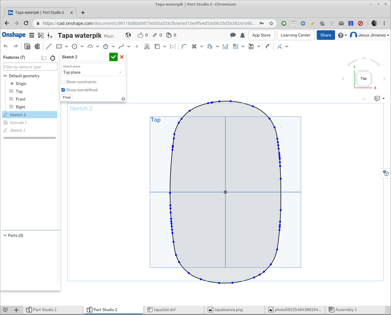
I've imported a DXF file into a sketch and it shows fine as a (I think) a closed loop of splines:

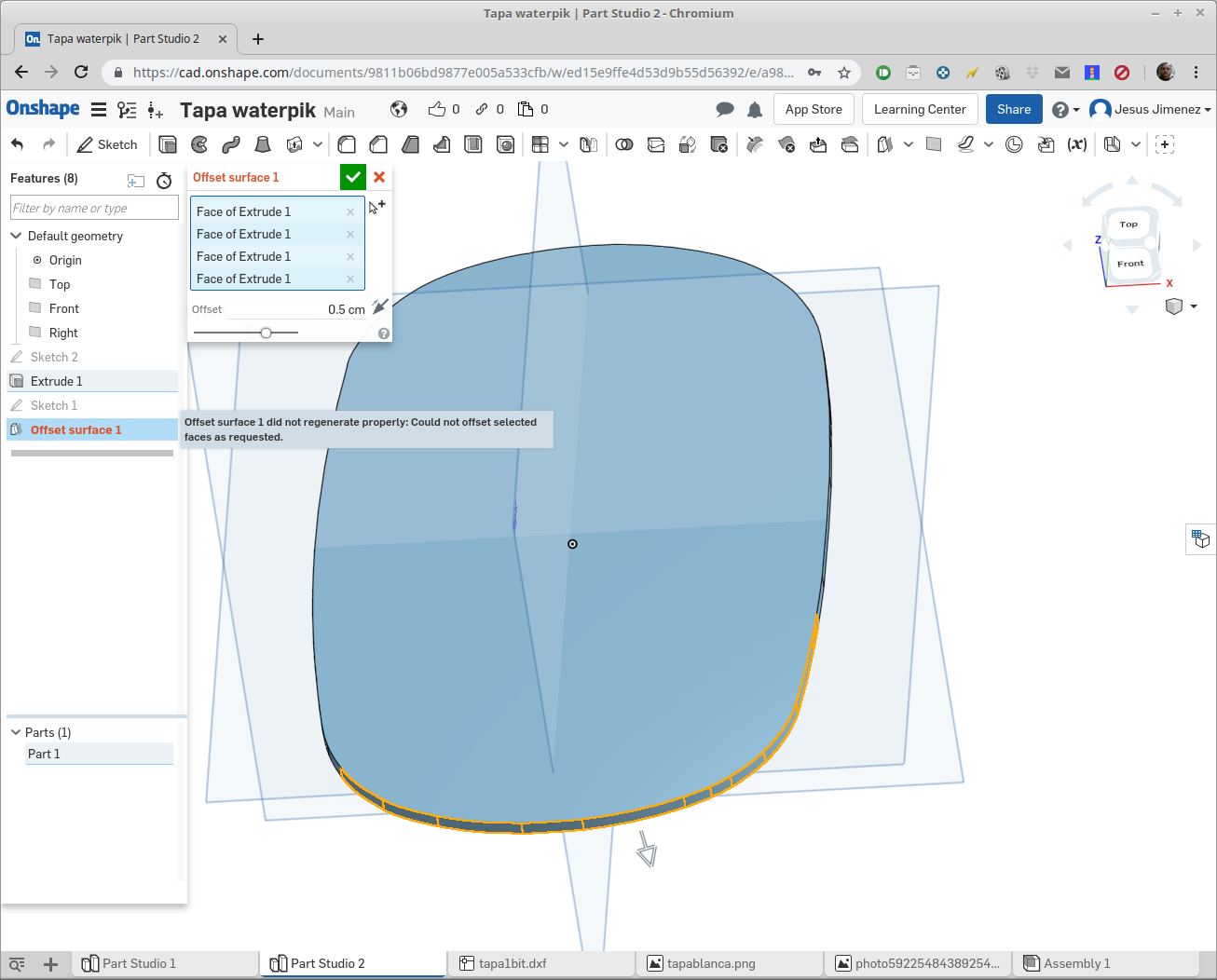
I can extrude it without problems, but now I need to create an offset around it, and no matter how I do it, Onshape ends up with errors. I've tried using sketch offset, and while preview shows it fine, after I confirm the operation it runs red and doesn't work saying "could not offset entities". I've tried using "offset surface" on the extruded sketch, but while most faces offset fine, some of them make Onshape show everything as red saying it's not possible:

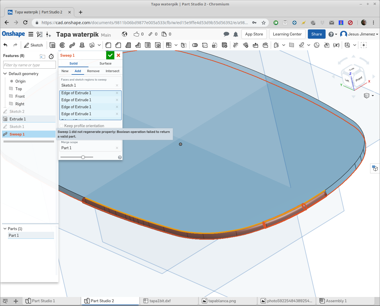
I've also tried sweeping a circle alongside extruded object's contour, without success:

Am I missing something, or it's just that Onshape doesn't manage sketch splines that well? it's getting very frustrating, no matter how I try it it just doesn't work, and for no apparent reason (that I can see).
Here's the document link if somebody needs to look at something: https://cad.onshape.com/documents/9811b06bd9877e005a533cfb/w/ed15e9ffe4d53d9b55d56392/e/a9823598b68956503ca73fdb
Thanks!
I've imported a DXF file into a sketch and it shows fine as a (I think) a closed loop of splines:

I can extrude it without problems, but now I need to create an offset around it, and no matter how I do it, Onshape ends up with errors. I've tried using sketch offset, and while preview shows it fine, after I confirm the operation it runs red and doesn't work saying "could not offset entities". I've tried using "offset surface" on the extruded sketch, but while most faces offset fine, some of them make Onshape show everything as red saying it's not possible:

I've also tried sweeping a circle alongside extruded object's contour, without success:

Am I missing something, or it's just that Onshape doesn't manage sketch splines that well? it's getting very frustrating, no matter how I try it it just doesn't work, and for no apparent reason (that I can see).
Here's the document link if somebody needs to look at something: https://cad.onshape.com/documents/9811b06bd9877e005a533cfb/w/ed15e9ffe4d53d9b55d56392/e/a9823598b68956503ca73fdb
Thanks!
Tagged:
0
Comments
HWM-Water Ltd
When working with Adobe Illustrator or Coreldraw for converting the logo from a vectorfile, AI. or EPS the export is not usable, lots of small segment's.
The solution I've found is simple, use Inkscape, that's open source software similar to Illustrator.
There are some tweaking checkboxes for exporting or save as DXF but the result are perfect.
By the way, the DXF file came from Inkscape (it was the result of vectoring a bitmap). Perhaps I messed up with vectorization settings, though DXF looked fine.
Thanks again to everybody, I didn't know what else to do, and you gave pretty solid advice.
Few tips you can find here:
https://forum.onshape.com/discussion/comment/49555/#Comment_49555
projektowanieproduktow.wordpress.com