Welcome to the Onshape forum! Ask questions and join in the discussions about everything Onshape.
First time visiting? Here are some places to start:- Looking for a certain topic? Check out the categories filter or use Search (upper right).
- Need support? Ask a question to our Community Support category.
- Please submit support tickets for bugs but you can request improvements in the Product Feedback category.
- Be respectful, on topic and if you see a problem, Flag it.
If you would like to contact our Community Manager personally, feel free to send a private message or an email.
Fillet-Two Surfaces or Fillet-Three Surfaces to add material near drafted features?
 christopher_owens
Member Posts: 235 ✭✭

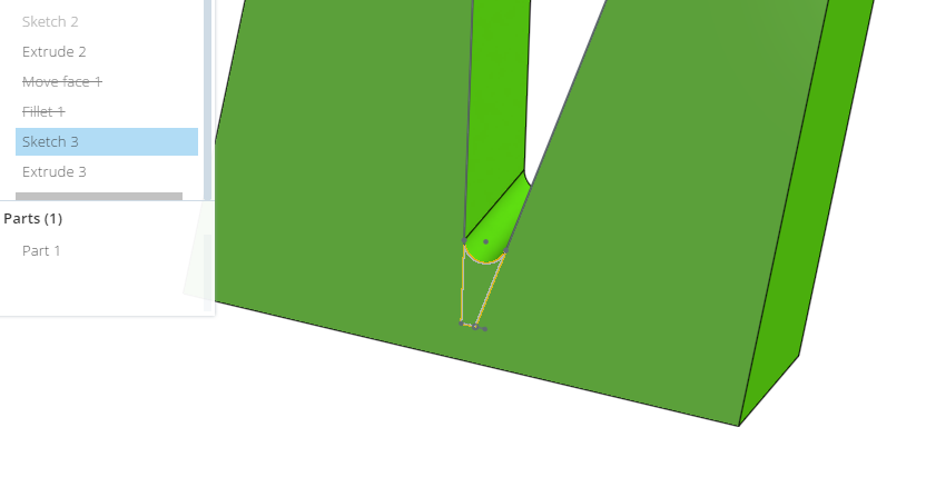
I created a simple model to show what I was wanting to do. I had two drafted surfaces that ended up forming a flattened V. I wanted to add some material in the valley by creating a fillet between the surfaces. Didn't see that option under Fillet. So I created a sketch (where you can create a fillet in the V sketched lines) and did an Extrude-Add. Easy enough to do in the simple model. Any thoughts on filling in a \-/ shape? I did try a Move Face on the actual model but that moved the entire face where I didn't want to increase the wall thickness. Guess I could do some Boolean caulking!
0
Best Answers
-
 andy_morris
Moderator, Onshape Employees Posts: 87
  Currently Onshape cannot add a fillet that would blend between the side faces to create the full round. I'll add you to that improvement ticket.
You can remove the bottom of the \-/ by using delete face and then filleting the resulting single edge. See my example file using remove face and fillet.Andy Morris / Head of Product Design / Onshape, Inc.5 -
 andy_morris
Moderator, Onshape Employees Posts: 87
  By re-ordering the fillet features to after the shell its easier to control how the radii on the internal faces work. You can also remove the slither faces and thin cuts by using a replace face to butt one face against its neighbor, though this will change the wall thickness slightly in certain areas.
Andy Morris / Head of Product Design / Onshape, Inc.5
Answers
I would do final shape directly in sketch or make flat V line construction figure and extend to sharp V to be able to fillet only one the bottom line.
You can remove the bottom of the \-/ by using delete face and then filleting the resulting single edge. See my example file using remove face and fillet.
and it retained the wall thinkness for the entire face! As you can see in the image the face extended beyond the V. Without the 'Cap Void' there was an opening where the face and wall use to be.