Welcome to the Onshape forum! Ask questions and join in the discussions about everything Onshape.
First time visiting? Here are some places to start:- Looking for a certain topic? Check out the categories filter or use Search (upper right).
- Need support? Ask a question to our Community Support category.
- Please submit support tickets for bugs but you can request improvements in the Product Feedback category.
- Be respectful, on topic and if you see a problem, Flag it.
If you would like to contact our Community Manager personally, feel free to send a private message or an email.
What mate can I use to create the correct movement in my linkages
 connor_macmurray
Member Posts: 11 EDU
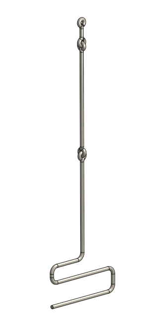
I am drawing up an automaton and the linkage required to move a component is as below:

The lower section only moves up and down which controls the upper one which makes a wing flap, but as the mechanism is moving back and forth the central section needs to allow for that movement at the connection points.
The link to the project is:
https://cad.onshape.com/documents/31f30302463325747d2c2c3b/w/6ef69631a6a7bdcbe148e925/e/2a17ef97183a05e2a89b946b
The part studios for the lower section and upper two sections, and the assembly of all three parts can be found in the 'Control rods and connectors' folder with the names 'lower wing control rod', 'middle and upper wing control rod' for the part studios and 'wing control rods' for the assembly.
The complete automaton is in the creatively named 'completed automaton' folder and you can see what the whole thing looks like.
If you animate the first revolute mate you will see what it is supposed to do.
Also the lower section of this control rod is supposed to engage with a crankshaft and it does, but not properly, I tried doing a tangent mate with the pin that drives it (as shown below) but I think I need to create some sort of offset path for it to get it to work properly. I just don't know how.
Any help with this would be greatly appreciated.
Connor
1
Answers
https://cad.onshape.com/documents/31f30302463325747d2c2c3b/w/6ef69631a6a7bdcbe148e925/e/1786e7e96449cfbbc7da0872
Without that, I'd use spherical joints for the loops & tangent for the bar/cylinder contact.
Also when an assembly is indeterminate, not enough constraints to determine one movement, I use the triad manipulator to move these components.
I believe once you get it defined, you might be better off using the manipulator to move it.
It'll be smoother motion with the manipulator.
I got it half working before i had to start my actual job, i'll try and finish the last mates up by the small joint at lunch.
Maybe I'm just not familiar enough with this toy's linkages. I've seen them before. But to me with the 3 piece linkage you have, it is like pushing chain. It tends to collapse on itself like a wet noodle
https://cad.onshape.com/documents/79661f41bc762ab11318f71c/w/353f776b245d01c0ca38427f/e/9fa1751d7a7ce7cced56ce36
It's working now
Pretty cool model by the way
HWM-Water Ltd
The idea eventually is to 3D print it and use wire for the linkages but I may have to scale it up for that if the wire is too thin. If I can get it to work it will be a project for students doing graphics in Year 9 in Australia (aged about 15) so that they can learn how to use the different tools in a CAD package and then customize their dragon using the skills they've developed. If I can get the little sod to fly consistently I'll do some legs for him too
HWM-Water Ltd
In the end I never needed to add any limits to the mates, they are free to move.
so the long middle arm should be the only "free" member.
On each end of the eyelets I added a small cube, you can see that in the post above.
The cube is a cheat, I don't rely on tangent mates in CAD most of the time, because they tend to do odd things (for example your cam on the lower linkage is crashing thru the follower on the wheel)
From there I added two mate connectors using the center mate connectors of the cube as axis
Here they are pulled apart.
the blue cube is revolute to the center of the vertical eye,
the other revolute is perpendicular, and uses the mate connector I added to the part in the studio