Welcome to the Onshape forum! Ask questions and join in the discussions about everything Onshape.
First time visiting? Here are some places to start:- Looking for a certain topic? Check out the categories filter or use Search (upper right).
- Need support? Ask a question to our Community Support category.
- Please submit support tickets for bugs but you can request improvements in the Product Feedback category.
- Be respectful, on topic and if you see a problem, Flag it.
If you would like to contact our Community Manager personally, feel free to send a private message or an email.
Fastened mate orientation error/bug/unexpected behaviour
 rune_thorsen229
Member Posts: 182 EDU
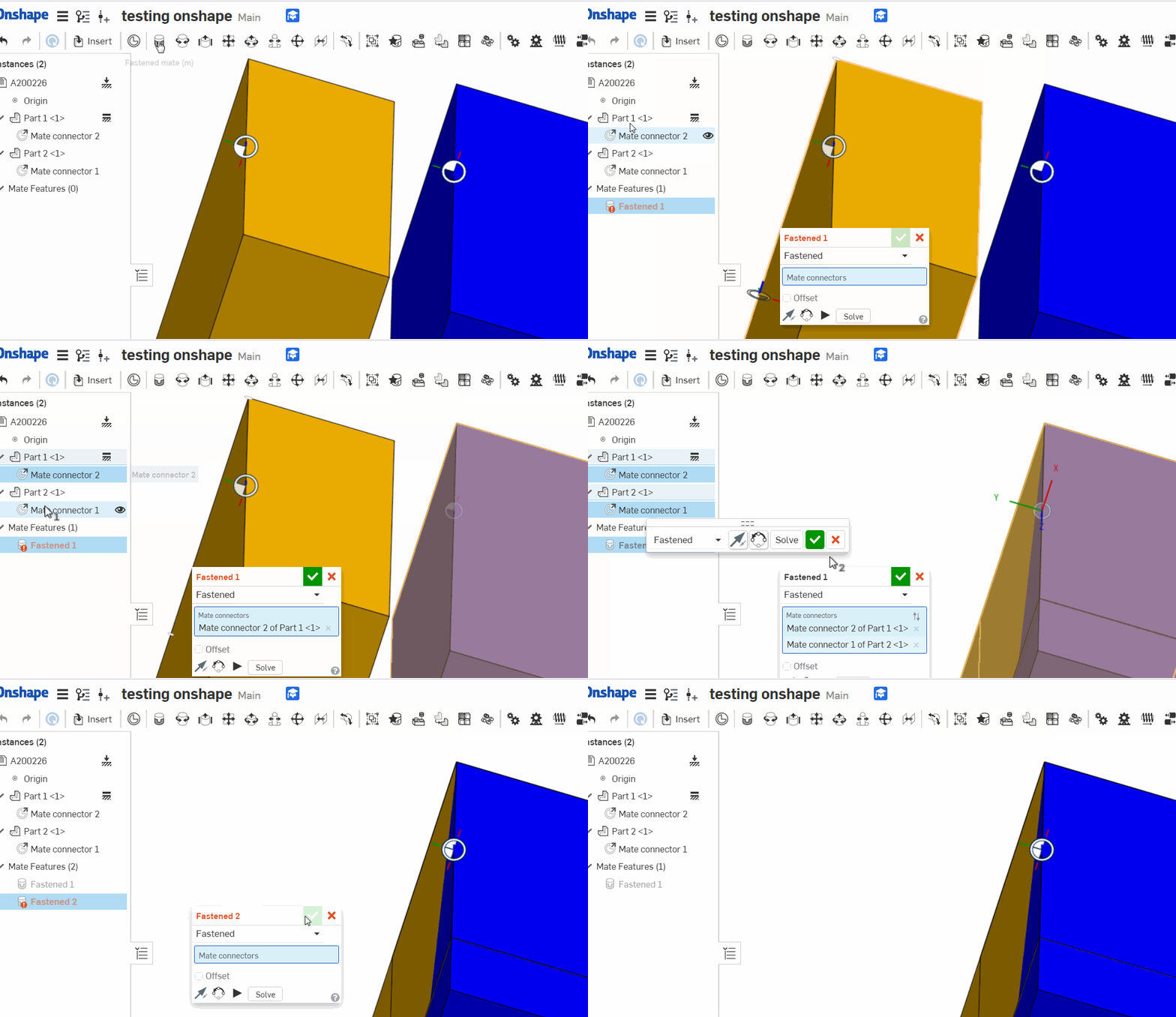
In assembly, when placing a carefully oriented fasten mate between two parts like these (notice the mate orientation)

I would expect this to happen

instead I get this

It depends on the starting position of the parts, but I consider it as a serious bug. You may argue that it is intended behaviour but it is rather illogical if it is a 'fasten mate' because it behaves like a revolute mate at the moment of solving.
I would expect a fasten mate to solve to match the orientation, place and plane as initially and only subsequently when the user changes orientation it should turn

I would expect this to happen

instead I get this

It depends on the starting position of the parts, but I consider it as a serious bug. You may argue that it is intended behaviour but it is rather illogical if it is a 'fasten mate' because it behaves like a revolute mate at the moment of solving.

I would expect a fasten mate to solve to match the orientation, place and plane as initially and only subsequently when the user changes orientation it should turn
Tagged:
1
Comments
Furthermore I encountered this problem where mates seems to give an unexpected offset
I use a line in a plane to place the mate
Document :https://cad.onshape.com/documents/dd4e620547fb95eb0b416aee/w/811d2761aa092256e78facf8/e/b82448a6521d3b3e1aaf5f93
HWM-Water Ltd
--------------------
As for your original topic. In general, the reason this is not a bug is:
Because each mate connector has 8 possible orientations relative to the origin point of each mate connector.
I understand your logic, default should be origins of both mate connectors are aligned X-X Y-Y Z-Z.
But if that were the case, then you will end up editing your mate orientation 99% of the time, rather than just pre-position the part and snap a mate. Much quicker the way Onshape currently has it.
Basically ignore the mate connector xyz position, treat it like a point, then flip/rotate until it is in the correct position.
This is the same behavior as I'm used to seeing in SolidWorks (pre-position before mating lest you fold your assembly into the fourth dimension)
with the exception of mating two origins with a coincident. Those behave as you expect mate connectors to.
https://cad.onshape.com/documents/dd4e620547fb95eb0b416aee/w/811d2761aa092256e78facf8/e/b82448a6521d3b3e1aaf5f93
"I understand your logic, default should be origins of both mate connectors are aligned X-X Y-Y Z-Z."
Exactly. I spent some time trying to understand why things were not perfectly aligned. Then I realigned the mates on my parts so they should be perfect when assembled just to find that I have to spend time realigning it all again.
Most of all what I don't understand is why the solver engine doesn't do that mating as first guess.
Secondly its faster selecting the relevant mates from the Instance list.
Finally I think it's exposes a error prone result when you cannot trust mates to align xxyyzz. I saw a comment thread where somebody are aligning thin sheets having the same probelm.