Welcome to the Onshape forum! Ask questions and join in the discussions about everything Onshape.
First time visiting? Here are some places to start:- Looking for a certain topic? Check out the categories filter or use Search (upper right).
- Need support? Ask a question to our Community Support category.
- Please submit support tickets for bugs but you can request improvements in the Product Feedback category.
- Be respectful, on topic and if you see a problem, Flag it.
If you would like to contact our Community Manager personally, feel free to send a private message or an email.
filled surface to create elliptical cap
 lucymarie_mantese
Member Posts: 24 ✭
lucymarie_mantese
Member Posts: 24 ✭
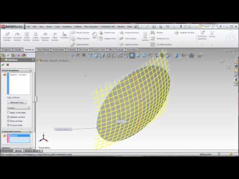
I am trying to create an elliptical cap the same as what is built using SolidWorks and described in this video link:
 https://www.youtube.com/watch?v=GT-1c_jFI1g
I have been able to create the cap in OnShape using the approach in the video but I believe OnShape does not have a "Filled Surface" feature and I am therefore unable to "fill-in" the elliptical cap. The image below is my current OnShape sketch. I would greatly appreciate help completing a solid model of the elliptical cap. Thank you.

I have been able to create the cap in OnShape using the approach in the video but I believe OnShape does not have a "Filled Surface" feature and I am therefore unable to "fill-in" the elliptical cap. The image below is my current OnShape sketch. I would greatly appreciate help completing a solid model of the elliptical cap. Thank you.
Tagged:
0
Best Answers
-
 nav
Member Posts: 258 ✭✭✭✭
Hi again @lucymarie_mantese I've changed the loft direction and got a better result, you can check the file (Second Tab) same link as the last post.
nav
Member Posts: 258 ✭✭✭✭
Hi again @lucymarie_mantese I've changed the loft direction and got a better result, you can check the file (Second Tab) same link as the last post.
Nicolas Ariza V.
Indaer -- Aircraft Lifecycle Solutions7 -
andrew_troup
Member, Mentor Posts: 1,585 ✭✭✭✭✭
@lucymarie_mantese
Regrettably, parasolid is not a format which retains sketches, feature editability etc.
There are (as far as I know) no 'non-native' or third party formats for any solid modellers which do any of these things.
You need to use the "Copy Tab" function to move parts between files: you will have to copy the whole studio, then (optionally) delete any unwanted parts
https://forum.onshape.com/discussion/357/how-do-i-transfer-a-part-studio-from-one-document-to-another
Or the new "Derive" facility is an alternative way to move them between tabs within a document.6 -
 brucebartlett
Member, OS Professional, Mentor, User Group Leader Posts: 2,148 PRO
@lucy_mantese Correct, surfaces are not yet supported in assemblies.
brucebartlett
Member, OS Professional, Mentor, User Group Leader Posts: 2,148 PRO
@lucy_mantese Correct, surfaces are not yet supported in assemblies.
Perform a thicken on the surface to get a part may work for you.
5
Answers
Step 1: Similar ellipse as yours, with a couple of guide curves
Step 2: Used the Loft Feature( surface)
With just one guiding curve (
With 3.... not nice
I suppose adding more guidelines will refine the profile. after having the surface fully define you can thicken the surface and obtain the solid.
Here is the public model so you can check out what I did.
https://cad.onshape.com/documents/68425bfa19834da49f6baeee/w/f59df980d1d64029a59c47fd/e/71244fc0a6ac48f98c538861
Indaer -- Aircraft Lifecycle Solutions
Indaer -- Aircraft Lifecycle Solutions
See here: https://cad.onshape.com/documents/ddd3a078ea084f7bbcb77c81/w/5bb6a8f91a4c4a9998a34659/e/0501df609f5e47f88e4fe8e1.
Check the tab V3.
I made the loft from the first edge of sketch 1, sketch 2 and then the second edge of sketch 1.
Guideline with sketch 4.
HTH
To create the section view at the end (Does not show up in the video above ) see here: https://www.onshape.com/cad-blog/a-look-within-onshapes-3d-section-view
Indaer -- Aircraft Lifecycle Solutions
One way to loft a smoother shape might be to create a number of loft profiles consisting of half-sections of the finished shape, but actually quarter-quadrants of an ellipse.
Each profile would comprise a short vertical line upwards from the ellipse centre, at its upper endpoint it would join (at a 90 degree corner), to a quarter ellipse, which would travel away from the central axis curving downwards, ultimately arriving vertically downwards to pierce the elliptical boundary curve. A horizontal line back to the centre would complete the profile.
These elliptical segments or quadrants (perhaps four in number) would radiate out from the central axis of the finished cap, sharing the same vertical leg, and the start section would also be the finish section. The only guide curve would be the elliptical boundary curve.
https://cad.onshape.com/documents/70f37346a0684b508492084f/w/891fd4042caa4cba9c676164/e/7cf781640cfd46f5bc40f0a9
Basically, it follows the same idea of swinging a loft about a common edge, (more like a sweep --except it seems sweep doesn't work this way, in Onshape - it fails with "Self intersecting" error)
but saving work by drawing only two loft profiles, at ninety degrees to each other, to make one quarter of an elliptical solid dome (same method could be used to create an elliptical surface, by omitting the two straight lines)
This quadrant was then mirrored about the two vertical construction planes to make a whole dome.
The resulting solid does conform to the elliptical curves at all the boundaries, so it is smooth in a gross way, unlike the result nav describes above as "not nice"
However, Onshape does not yet allow making a loft tangency strictly normal to the start and end planes, and consequently when zebra stripes ("curvature visualisation") are added to the resulting body, it is clear that it is not optically smooth across the junctions. (You can see the same in nav's otherwise excellent v2 result, but he has only half as many junctions as me)
I imagine that my first suggested method (producing a closed loft through four profiles all at ninety degrees) would give a smoother result, except that there would (I expect) still be a discontinuity at the seam between the first and last profiles. I'll check it when I get a spare moment.
The common axis of all the loft profiles is shown in red.
It was a bit tricky to set up: I had to "match vertices", specifying the outer ends of each loft profile, before the loft would accept sketch 1 (the closed, complete ellipse on the "Top" plane) as the guide curve
The model is public, at:
https://cad.onshape.com/documents/bf7b6aac098b412db7ba7d55/w/fcb46e5d13b64f5ab40412e7/e/73b058c2297a4052b4f801ea
.
Both models are smooth at the location of minimum curvature, on top, but this is not the case at the pointy ends.
The resulting difference in smoothness at the ends is barely detectable, as the zebra stripes show, but perhaps might be noticeable in a highly finished part, or a metal injection mold tool. Probably what's more important is that degenerate points can cause downstream problems -- either within the modelling app (especially when you try to thicken a surface) or for (say) CAM processing of the result.
I don't think the degeneracy here would be enough to cause such problems, but I raise it as an example which may interest some who will encounter more serious instances.
Because of the lack of tangency controls in Onshape at present, it may also illuminate some additional loft options in a way which may help people get better results in the meantime.
For those wishing to know more about degenerate singular points (which is essentially a mathematical breakdown in the description of the surface where all the splines converge to a point) there is some good material on the www.
Here's one I just found:
The problem when the splines converge is a bit like a contour map where the contours converge to a point: there is no way of computing what the local slope is at that location - and "does not compute" is a problem for computers (unlike humans, who can shrug it off)
1. Sketch an ellipse and fully define it. Make sure that the quadrant points are aligned some way (I made them horizontal on creation).
2. On an orthogonal plane, start a sketch. Sketch an arc that pierces the ellipse on the ends (use the pierce constraint, not the coincident constraint). Use the split tool to split the arc and use a vertical or horizontal constraint on the point created to be in the same place as the center of the ellipse. Fully dimension the center of the arc.
3. On the other orthogonal plane, sketch an arc that pierces the ellipse at the ends. Select the arc as well as the arc created in the previous sketch and pierce them. Use the split tool to split the arc and make that point coincident with the point created on the previous arc.
4. Start a loft. For the profiles, select the elliptical face first and the split point second. You'll get some cone-ish looking thing. (I'm doing it as a surface loft, you can do it as solid if you wish.)
5. Add the four arcs (two arcs that were split in two) as guides. This should give you the shape you were looking for.
6. From here, you just need to do a two directional extrude of the elliptical sketch. One direction goes up to the surface you just created. The other goes as far as you want in the other direction.
Indaer -- Aircraft Lifecycle Solutions
Nice demo, great method, thanks a lot.
I did briefly wonder whether to have a crack at that: I recall successfully developing it for a Solidworks Model Mania challenge, many years ago, and subsequently feeling vindicated when the 'official answer' used the same dodge!
I've redone the model using my less elegant method at
https://cad.onshape.com/documents/bf7b6aac098b412db7ba7d55/w/fcb46e5d13b64f5ab40412e7/e/73b058c2297a4052b4f801ea
using circular arcs like yours, rather than elliptical arcs - I should have taken the time to view the OP's clip, whereas I cheated by looking at the geometry others had posted -
A question Jake, if you're still looking at this thread: I notice that the resulting solid (whether from your method or mine) has a lot of short edges around the sharp edge between the elliptical extruded walls and the domed top. Here are some of them, on your model:
When I run a simple fillet (with tangent propagation) around this edge, I nevertheless get a single face on both models, which is pleasing -- and not entirely expected.
However, if I try to achieve better curvature continuity with a conic fillet, I do get a broken face, as expected. This happens in both cases, although rather more irregularly with your model - the duck egg blue one)
I'm guessing the problem arises from a hit and miss situation where the elliptical extrude meets the edge of the surface resulting from the loft? Overlapping minutely at some locations and undershooting in others, due to the an algorithmic computation inevitably delivering a slightly variant result from an analytic one, possibly?
I tested this by creating a slightly smaller ellipse for the extrude, and sure enough, I got a clean single edge, which even a conic fillet was able to sweep in one go. (refer the tab labelled "Smaller ellipse extruded" in my linked model)
I used to encounter such problems all the time in Solidworks. I wonder if solid modellers of the future might alleviate such computational shortcomings, perhaps by temporarily extending the internal representation of capping surfaces slightly beyond the profiles extruded up to them? Saving us from confusing outcomes, which currently lead to us having to perform laborious and somewhat arcane workarounds...
I don't have a good reason why conical fillet are not able to remove redundant edges/surfaces while non-conical fillets can. We have plans to upgrade our implementation of conic fillets in the future, which could potentially remedy the situation.
As for the short edges that are shown, I believe that is the result of loft being an approximation and not being fully capped by the ellipse. Doing the extrude from the ellipse up to the surface right on the boundary most likely hits differences at that edge based on the precision. Rather than creating one single edge, it creates a bunch of them.
for confirming that it's a boundary representation mismatch.
Question: Can you see any merit in my suggestion that the internal representation of the cap surface be temporarily extrapolated/extended for the purpose of delivering clean edges?
It seems to me something along these lines must already be happening, or the extrude would fail altogether? (I recall this happening routinely in the early days of Solidworks)
It would be a plague, in a complex curvy model, if a number of edges end up being segmented in this way. There's more at stake than would be addressed simply by upgrading conic fillets, sweeps etc... paper over cracks is better than no paper, but not as good as no cracks.
I think we should be able to get better edges here. Could you please submit a feedback on these documents. We'll work on it. Thank you.
Yay! go the dream team! Will submit, con mucho gusto
1) I opened the public file @erwin_1 made available in the thread above (thank you erwin_1)
2) I made a private copy.
3) I exported one of the parts (Tab 1) as Parasolid and downloaded it to my computer.
4) I imported the part it into a separate OnShape file I am working on.
5) The imported part shows up as a separate tab. But it does not include the specific sketch information (Loft, etc), it only shows up as "Import".
6) I then tried to include the imported part in an assembly but it does not show up in my assembly list.
Is my import/export procedure incorrect? Thank you.
R/ Check if the part you're trying to insert in assembly is a surface, at the moment OS assemblies do not recognize assemblies, this might be the reason is not showing up in your assembly list.
Indaer -- Aircraft Lifecycle Solutions
Regrettably, parasolid is not a format which retains sketches, feature editability etc.
There are (as far as I know) no 'non-native' or third party formats for any solid modellers which do any of these things.
You need to use the "Copy Tab" function to move parts between files: you will have to copy the whole studio, then (optionally) delete any unwanted parts
https://forum.onshape.com/discussion/357/how-do-i-transfer-a-part-studio-from-one-document-to-another
Or the new "Derive" facility is an alternative way to move them between tabs within a document.
@nav suggested to see if the imported part is listed as a surface and it is. Is that the reason it can't be added to an assembly?
I'd appreciate any suggestions. Thank you again.
Perform a thicken on the surface to get a part may work for you.
Twitter: @onshapetricks & @babart1977
I am quite new to CAD and OnShape (only a few weeks under my belt), and have been having decent luck with getting some ideas I have drawn out (lots of trial and error).
I am currently working on an elliptical cap like the examples by @jakeramsley and @andrew_troup, and have used a copy of the sketch from Andrew's example to build mine from. I have changed the length/width dimensions so the long end is north/south as opposed to east/west in the example for consistency with all of my other parts, but height remains the same.
The constraints seem to have adjusted as well, except for a "Sketch could not be solved" error in sketch 2 (see screenshots). However, I am able to run subsequent operations fine.
I have not had any luck figuring out what it is complaining about. While in a perfect world I would love to fix it, is it really necessary given the extrudes and shell have worked fine?
Thanks for any insight you can provide,
Jody