Welcome to the Onshape forum! Ask questions and join in the discussions about everything Onshape.
First time visiting? Here are some places to start:- Looking for a certain topic? Check out the categories filter or use Search (upper right).
- Need support? Ask a question to our Community Support category.
- Please submit support tickets for bugs but you can request improvements in the Product Feedback category.
- Be respectful, on topic and if you see a problem, Flag it.
If you would like to contact our Community Manager personally, feel free to send a private message or an email.
Curvature Visualisation (Zebra Stripes)
 nav
Member Posts: 258 ✭✭✭✭
Hi guys could you please share some tips on how to properly use the curvature visualisation (Zebra stripes) tool in OS ? Not sure how to properly use it, thanks.
Edit1: How to know if the surface(s) are smooth, what else can I check with this tool ?
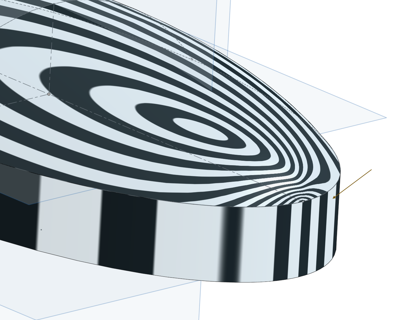
Edit 2: For example the extruded surface shown by the arrow, what do the stripes mean (smooth not smooth, continuous, contact ?) Thanks again For
For
Edit1: How to know if the surface(s) are smooth, what else can I check with this tool ?
Edit 2: For example the extruded surface shown by the arrow, what do the stripes mean (smooth not smooth, continuous, contact ?) Thanks again
 For
For Nicolas Ariza V.
Indaer -- Aircraft Lifecycle Solutions
Indaer -- Aircraft Lifecycle Solutions
Tagged:
0
Comments
http://www.calgaryherald.com/life/Photos+Iconic+Aston+Martin+celebrates+years/7803367/story.html?rel=8821076
There are two ways they help us: firstly in the middle of a face, wiggles indicate deviations from "Fairness". By manipulating the orientation of the model, you can discover whether it's a bulge, a depression, a crease/wrinkle, or a wave. It helps to have some experience of interpreting contour maps (eg climbing or hiking navigation 101)
Secondly at a junction between faces: if the stripes do not line up, there is no continuity. If they line up but have a kink, there is tangent continuity (sometimes called C1). If they flow through the junction as if it were not there, there is curvature continuity (C2 or higher).
Tangent continuity, C1, means that the two splines defining the face to either side of the junction share the same local direction at that junction ("slope", if you imagine them as being graphed)
C2 curvature continuity means that the rate of change of slope (aka the "first derivative", in calculus terms, or "curvature" in surface modelling) has the same value immediately to either side of the junction.
C3 curvature (IIRC) means the "second derivative" (the rate of change of curvature) has the same value either side.
C1 was once the gold standard in car panels and consumer products, then C2, now C3 is more or less the minimum requirement.
I leave it to you to decide whether that makes the world an entirely better place!
Indaer -- Aircraft Lifecycle Solutions
I went back and edited C2 and C3 slightly, so they might make a bit more sense to the non-maths-geek.
Well done (especially your closing statement), Thanks.
I do feel a bit guilty, though, and in deference to the feelings of maths geeks (even geeks have feelings!) I had better square things up by addressing a few words to them:
Yes, you're perfectly right: Slope is already a derivative, the first derivative, of the function being graphed.
Which, you will no doubt be impatient to see acknowledged, was how C1, C2 and C3 continuity got their labels: these denote continuity of the first, second and third derivatives, at a given point, of the function defining each spline.
There. Phew. Honour is satisfied.
>CANCEL GEEKSPEAK
Analytic faces are based on the primitive geometry of prisms, cylinders, cones and the like, whereas
Algorithmic (no, Al Gore didn't invent them!) faces are spline based, freeform shapes.
Algorithms, as face definitions, introduce limitations which may not be crisply definable (and hence a computational nightmare): for instance, if such faces have to be extrapolated by the software beyond the user-defined boundaries (the original perimeter edges), the results are indeterminate and hence unpredictable, and sometimes topologically impossible.
Solid modellers are really disguised surface modellers, which automate a couple of laborious aspects of surface modelling, such as keeping track of which side of each face has solid material behind it, and whether adjoining surfaces are properly trimmed to a single common edge. (A group of adjoining surfaces cannot meaningfully define a solid unless they are "watertight"). But it is very computationally wasteful, and potentially confusing for the user, to employ solid features to create bodies whose faces are primarily algorithmic. This is mainly why pure surface modelling becomes indispensable for such bodies.
Back closer to the current topic: the OP in the other related thread presented a problem which ideally would be solved analytically. A tri-axial ellipsoid is a geometric primitive. However this particular shape is not yet available "off the shelf" in Onshape (unlike, say, Solidworks, where the "Dome" feature creates elliptical domes analytically) ... so we are forced to use algorithmic tools (like Loft) in cunning ways to get as near as we can to the pure mathematical perfection of an analytic face.
Zebra stripes are a key tool in this arsenal ... but it also helps, over time, to cultivate a deeper appreciation of the nuances of solid geometry.
I'm almost completely back on track now: all I wanted to clarify, in response to a question in the OP of this thread I didn't get around to answering: zebra stripes do not (as far as I know) have any useful application to analytic faces, like the faces of an extrude or, for that matter, a tri-axial ellipsoid. Such faces are incapable of being created imperfect, (one reason they fascinated the ancient Greeks) so it proves nothing to check them.
"Revolve" produces analytic bodies, if the sketch is a geometric primitive (including a half-ellipse)
so we COULD produce an analytic tri-axial ellipsoid by rotating such a sketch, and then scaling it in z but not x or y
We could even start with a simple circular arc, revolve to produce a hemisphere, and then scale it non-uniformly in y and z. Naturally we can also trim the height if we don't want exactly half an ellipsoid)
However as far as I know (and it's hard to keep up!) we don't yet have non-uniform scaling of bodies as an Onshape option.
Theoretically there will be a slight degradation from perfection when applying scale factors to an analytic body, particularly large unequal factors, but I've never known it to cause a downstream problem such as you get from degenerate points, discussed in this thread:
https://forum.onshape.com/discussion/1327/filled-surface-to-create-elliptical-cap#latest
ps. That Aston of yours looks also good..
Mathematics for Computer Graphics Applications
by Michael Mortenson
it seems to me they're saying something considerably simpler, which happens to have useful explanatory power:
for C0, the parametric function is the same for both splines at the junction, so the splines meet at the junction
for C1, the first derivative of the function is the same for both splines at the junction, so the splines share the same direction at the junction
for C2, the second derivative is the same ..., so they share the same curvature...
for C3, the third deriv is the same..., so they share the same rate of change of curvature (in other words, if we displayed curvature combs, the slope of the tops of the combs would match at the junction)