Welcome to the Onshape forum! Ask questions and join in the discussions about everything Onshape.
First time visiting? Here are some places to start:- Looking for a certain topic? Check out the categories filter or use Search (upper right).
- Need support? Ask a question to our Community Support category.
- Please submit support tickets for bugs but you can request improvements in the Product Feedback category.
- Be respectful, on topic and if you see a problem, Flag it.
If you would like to contact our Community Manager personally, feel free to send a private message or an email.
Phantom Discontinuity At Mirrored Surface Seam
 matthew_stacy
Member Posts: 489 PRO
Why are faces generally split at the seam when a surface is mirrored?
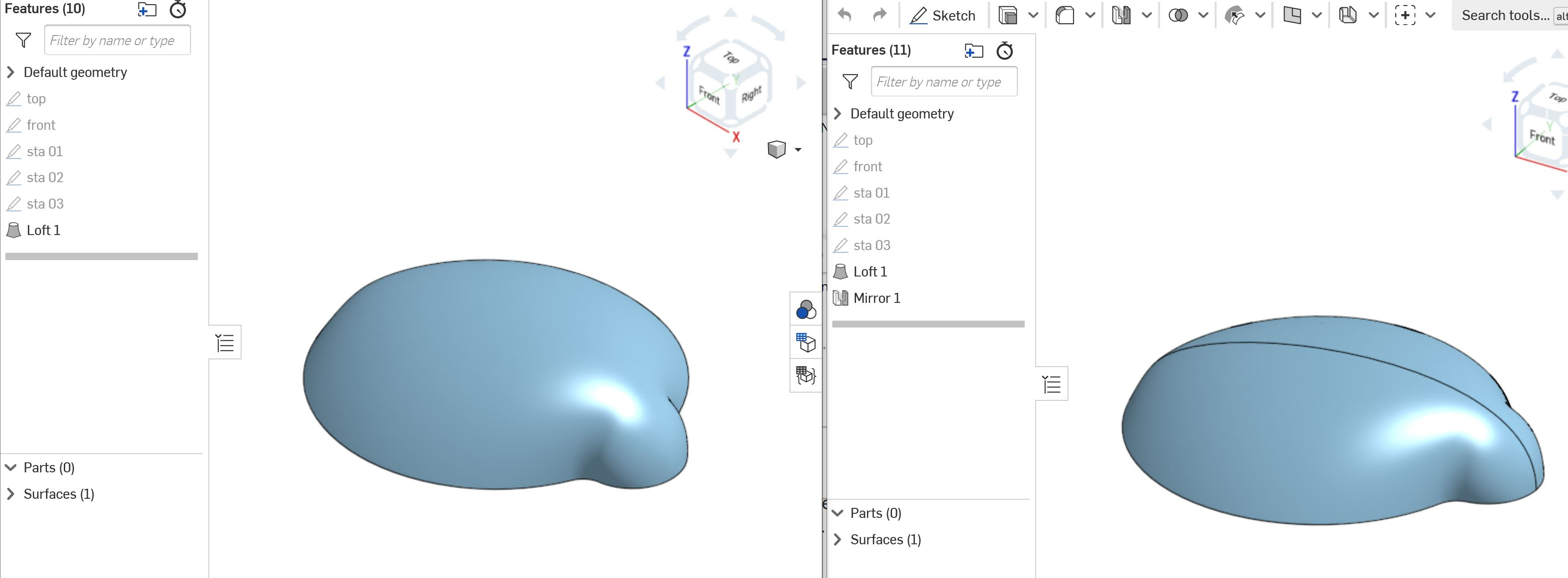
In this example (https://cad.onshape.com/documents/51b9043cee7e3dbb60c1192c/w/31a742765743fe1fd962a776/e/7ad5ec31da1120d731ab044c) a lofted surface is shaped with guide curves. In one Part Studio the guide curves are sketched "full-span", symmetric about the front plane. The result is a single smooth contiguous surface. In a second Part Studio only half of each guide curve is sketched. When this surface is mirrored there is a visible seam at the plane of symmetry. Turning on curvature visualization indicates that the underlying geometry appears to be identical in both Part Studios, but one has a seam.
Unless I am missing something these "half-span" guide curves are identical to their full-span brethren, with exactly the same tangency and curvature constraints where they intersect the plane of symmetry. So why is the mirrored face split? And is there a way to merge them into a seamless whole?

0
Best Answers
-
 NeilCooke
Moderator, Onshape Employees Posts: 5,942
  @matthew_stacy - extruded and revolved surfaces are analytical geometry i.e. their shape can be described with simple math. A surface created by splines is a whole different ball game and @Evan_Reese is right - it is not possible (or not easy at least) for Parasolid to recreate the math for the whole mirrored surface with perfect accuracy.Senior Director, Technical Services, EMEA0
 -
 EvanReese
Member, Mentor Posts: 2,715 PRO
Interesting point, Neil. I hadn't fully thought about what's happening when it merges those simpler surfaces. Is it making a new surface and replacing the old one (including IDs and all that)?
Either way, I don't personally think I'd get a lot of value out of making symmetrical surfaces with no seam any more than I would by removing tangent edges of fillets. The only time I would want to do something like that would be to have a clean single surface to drive an Attractor Pattern feature with. To map a pattern across multiple surfaces I may have to spend a decent amount of time making that clean base surface that's similar enough to the parts I want to texture.0
Answers
In your second example, you made a surface that's half the size and it's UV curves look like this. see how the UVs are all smushed together?
To merge them into a whole, you'd have to recreate a similar (but not mathematically identical) surface to replace them with. I actually don't recommend this and prefer to have a split line where I want true symmetry, because it is possible for the part to look symmetrical, but not actually be symmetrical, which can cause other issues down the line. The split line is a clue that it's perfectly symmetrical.
The Onsherpa | Reach peak Onshape productivity
www.theonsherpa.com
Either way, I don't personally think I'd get a lot of value out of making symmetrical surfaces with no seam any more than I would by removing tangent edges of fillets. The only time I would want to do something like that would be to have a clean single surface to drive an Attractor Pattern feature with. To map a pattern across multiple surfaces I may have to spend a decent amount of time making that clean base surface that's similar enough to the parts I want to texture.
The Onsherpa | Reach peak Onshape productivity
www.theonsherpa.com
The Onsherpa | Reach peak Onshape productivity
www.theonsherpa.com