Welcome to the Onshape forum! Ask questions and join in the discussions about everything Onshape.
First time visiting? Here are some places to start:- Looking for a certain topic? Check out the categories filter or use Search (upper right).
- Need support? Ask a question to our Community Support category.
- Please submit support tickets for bugs but you can request improvements in the Product Feedback category.
- Be respectful, on topic and if you see a problem, Flag it.
If you would like to contact our Community Manager personally, feel free to send a private message or an email.
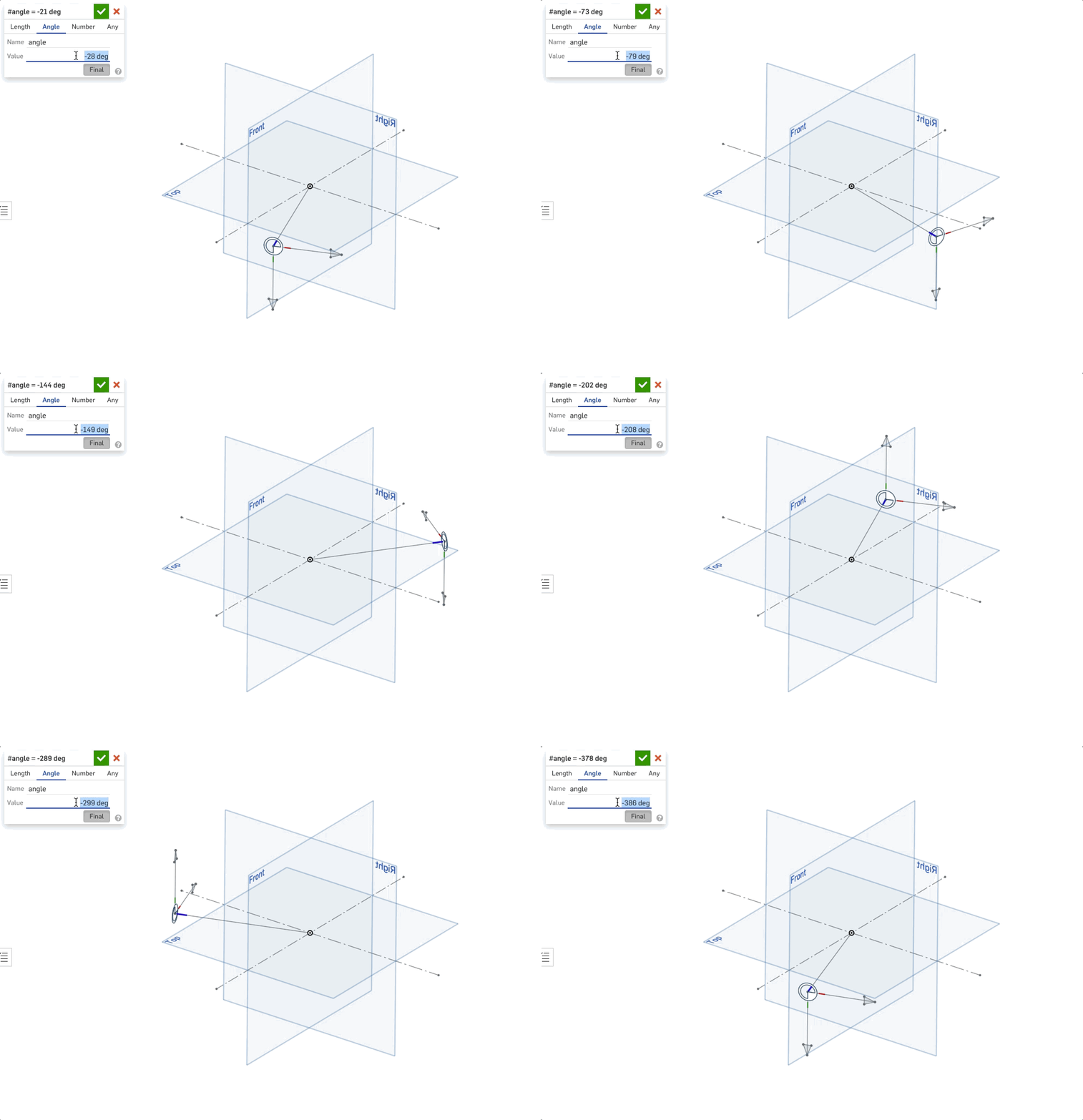
Why does this mate connector flip 180° depending on the curve angle?
Why does a mate connector made on a curve flip depending on where the curve is relative to the front plane? I know I could set the secondary direction of the mate connector to the top plane to probably fix this, but it's I think it's really a demo of the curve's orientations changing which causes downstream issues for me that can't be easily fixed.
I made this simplified example document of the issue I'm having, but this is actually causing some pretty big headaches on a pretty big project for me right now. I've got a master sketch that is driving all kinds of things including some patterns and things like that. This issue seems to also mess up some of the replicate features in our assembly, since instances on the other side of the front plane are all flipped the wrong way and the mate features can't be manually flipped.
Anybody know why it's this way?

1
Best Answer
-
 ilya_baran
Onshape Employees, Developers, HDM Posts: 1,254
  It's not just 3D CAD, it's a mathematical issue -- there is just no way to assign a coordinate system continuously given one axis: https://en.wikipedia.org/wiki/Hairy_ball_theoremIlya Baran \ VP, Architecture and FeatureScript \ Onshape Inc1

Answers
The Onsherpa | Reach peak Onshape productivity
www.theonsherpa.com
The Onsherpa | Reach peak Onshape productivity
www.theonsherpa.com
.
Let's say you have nothing to reference, a blank slate, and you want to create a plane normal to Z:
So you cross Z & X to create Y, then Z & Y to create the real X. This is your algorithm, a simple triple product, a mate connector.
Now you want a plane normal to X:
Use your algorithm and X=0 and everything crashes. At some point you have to be discontinuous and change your reference to Y.
In an empty world, you cannot have a continuous expression making a simple decision to create a plane. You have to decide whether you're crossing with X or Y. So when do you decide?
//create sketch
var xDir;
if (abs(evAxis(context, {"axis" : MCs[0]}).direction[1]) > .707) xDir=vector(1, 0, 0); else xDir=vector(0, 1, 0); //flip x along y
When I wrote the cable featurescript, the cable rendering would crash every so often. Since I was creating the sketch relative to the world, I have to decide which to cross with X or Y. After I added this, it became more robust, at least for sketch orientation creation.
I think what your seeing is this basic 3D artifact animated. In 3D cad you have to make this decision at some time. Aligning X is always a real pain.
The Onsherpa | Reach peak Onshape productivity
www.theonsherpa.com
@ilya_baran "hairy_ball_theorem" where do you find this stuff?
export function perpendicularVector(vec is Vector) returns Vector<br>precondition @size(vec) == 3;<br>{<br> if (vec[0] is ValueWithUnits)<br> vec = [vec[0].value, vec[1].value, vec[2].value] as Vector;<br> if (squaredNorm(vec) < TOLERANCE.zeroLength * TOLERANCE.zeroLength)<br> return vector(1, 0, 0);<br> var different = vector(0, 0, 0);<br> // The numbers are "random" and close to 1. They're to avoid instability in cases likely to occur.<br> if (abs(vec[0]) > 1.036663652861932668633 * abs(vec[1]))<br> {<br> if (abs(vec[0]) > .951702989392233451722 * abs(vec[2]))<br> different[2] = 1;<br> else<br> different[1] = 1;<br> }<br> else<br> {<br> if (abs(vec[1]) > .920419947455385938102 * abs(vec[2]))<br> different[0] = 1;<br> else<br> different[1] = 1;<br> }<br> return normalize(cross(different, vec));<br>}I think they're checking for 2 parallel vectors which will divide by zero can crash. Not a good thing.