Welcome to the Onshape forum! Ask questions and join in the discussions about everything Onshape.
First time visiting? Here are some places to start:- Looking for a certain topic? Check out the categories filter or use Search (upper right).
- Need support? Ask a question to our Community Support category.
- Please submit support tickets for bugs but you can request improvements in the Product Feedback category.
- Be respectful, on topic and if you see a problem, Flag it.
If you would like to contact our Community Manager personally, feel free to send a private message or an email.
Custom Feature: Cable/Wire Routing
Comments
-
@NeilCooke,
Still working on resolving this, I just realized that the extrudes for both stripped ends are created on the same end of the wire. Also a strip length set to 0 causes an error (extrusion fail in the console).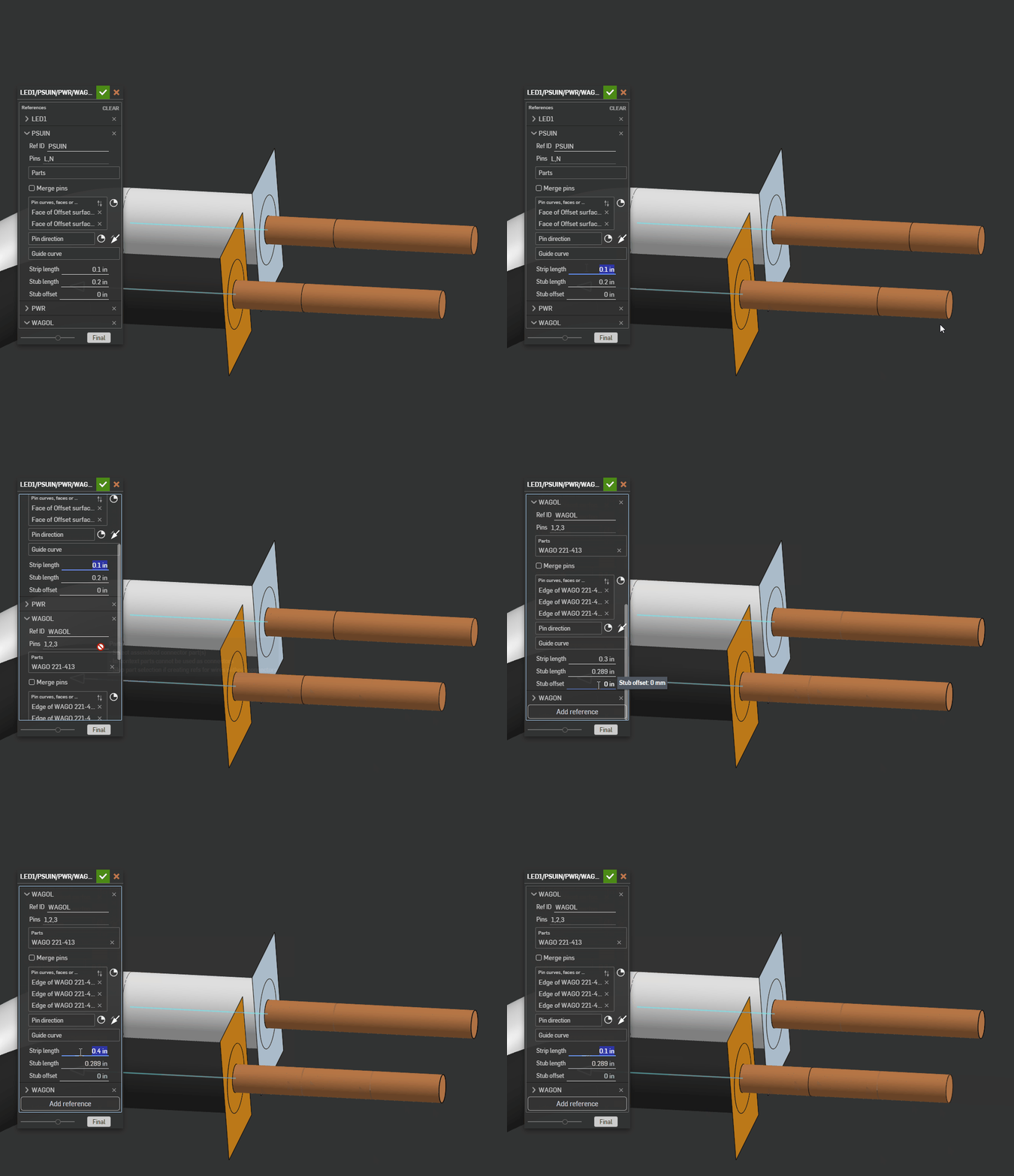 0
0 -
@eric_pesty thanks - I did encounter that recently and fixed it in my test examples - let me look again.
Senior Director, Technical Services, EMEA0 -
@eric_pesty @Matt_NC I have just pushed an update to fix the stripped end appearing on the same end of the wire - the logic that was there for years had no right to have ever worked, but now it should be fine.
@eric_pesty The "connector requires library update" is a catch-all. In this instance, your WAGO connectors are essentially splices (or daisy-chained connectors with more than one wire attached) which is not currently supported. I did mention it in the video but did not point out that this also includes splices. I am currently working on this, but it is a challenge.
I also fixed the zero length strip value which ended up being a typo in a variable name.
Senior Director, Technical Services, EMEA1 -
Thanks for the quick update, the stripped ends are back where they should be!
I wasn't quite clear what you meant in the video about the "daisy-chain" part but I think I get it now!0 -
@eric_pesty I also made some adjustments to the Harness layout feature so now you can at least flatten USBIN. The issue there was related to the Wire ref USBBHD having a tiny stub length and a stub offset of zero, therefore leaving a small gap. It works now, but it is better to at least adjust the stub offset to a negative value to ensure the wire touches the back of the connector.
Senior Director, Technical Services, EMEA0 -
Thanks Neil, I'll keep the stub offset in mind.
I was jus messing around with the USB, I don't actually need to flatten this as it's just an OTS part I just use the wiring feature for these as it makes for a nicer workflow.0 -
Ok, I've had a chance to experiment a bit more and submitted a couple tickets about specific things I'm seeing but I also have a couple "higher level" questions.
- What I am working on right now is intended to be assembled "in-house" and what I have done in the past is to create an assembly with the wires in a "straight" representation and then used assembly items to indicate qty. of each wire required. This also results in a sort of "library" of wires being created through the items. In the example there is a table showing the lengths of each "run" but that doesn't provide a rolled up qty of each wire or show a part number for the wire to use. Is there a plan for addressing this?
- Ideally we would have the ability to have pre-defined library of wire and also support for multi-conductor "wires" (i.e. OTS jacketed cables).
- You mention adding labels and boots, etc… but with this not being an assembly, what is the intended way of showing these in the drawing (especially if they need a part number/description attached)? Would they have to be defined specifically and/or tagged with the right properties to show up in the "cut-list"?
- How is this intended to function with release management? Right now the 3D harness that would be inserted in the assembly is pretty much completely detached from the straightened version and the drawing so I am wondering how to best manage part numbers and revisions.
Thanks for the continued effort on this, this is starting to look quite polished!
1 -
I can confirm it has fixed the issue for me 👍🏻
0 -
Did the "network" feature of this feature script get removed?
0 -
@NeilCooke, Thank you for your wonderful work on this project. I have been using it for a few years now and it has really helped me collaborate with my colleagues on electrical integration. I also really appreciate how often you release improvements and fixes.
I am currently evaluating how the new Harness Layout feature could help me ditch my reliance on another cable drawing solution. I am capable of producing drawings for many of my cables using this feature, but have one major obstacle: I can't include an exhaustive BOM on the drawing. Specifically I need the drawing to list part numbers and specifications for connector contacts, wires and multi-conductor cables. I have updated my connector library to include values for contact PNs and descriptions, but cannot get them to populate in any of the tables.
Additionally, many of the connectors I use in my harnesses don't have only one single contact part number associated with them, some require contacts for different wire gauges, or different finishes, but are used in the same connector and must be called out in the drawing in the connector table to be associated with a specific contact position. As such it would be very useful if I could define more than one contact associated with each connector and assign them to specific contact positions in the wire data .csv or even better, in the Wire Ref feature. I assume that since this feature is new, you have some of these things in mind for future updates, but wanted to ask if you may suggest any workarounds. Thank you!
1 -
Hi Brian, the "network" feature still exists, but it detects it automatically (if there is more than one route through the "clip", then it's a network). Let me know if it's not working as expected.
Senior Director, Technical Services, EMEA0 -
Hey Dan, that is totally doable. You should be able to configure contact/terminal part numbers in the connector feature, but there is no current way to set different terminals in the same connector.
Senior Director, Technical Services, EMEA0 -
A tip I've used; I set up a configured variable that is defining the PN and description for the terminals. Such that pin terminal types can be selected with configurations in the insert. It's a little clunky to set up but works well.
1 -
I've been wanting to refactor the entire codebase for a while now because I've never really been happy in the way I was storing/retrieving and manipulating metadata. I've tried a few times in the past and had to give up, but thanks to the FeatureScript MCP Server, the refactor is complete and it found a couple of performance optimisations along the way, specifically in editing and dragging cable segments. I am very impressed. Apart from some speed improvements and a couple of bug fixes, you shouldn't see any difference - if you do please let me know ASAP!
Changelog for release 1.219.0
⭐️ MCP optimisation
⭐️ Clip segment fix when using Composite curves
⭐️ Arcadia output fixSenior Director, Technical Services, EMEA0 -
I'd be interested in hearing more about the refactor itself, specifically the differences in metadata storage that you're happier with post-refactor. I've got some things I've been doing with metadata in a few features that feel janky but I haven't run into the counter case that breaks those features yet.
0 -
For every feature, and sometimes several times per feature, I was calling setAttibute/getAttribute (I store all the data as attributes on the Part Studio origin) to populate an array of a specific data type. What I asked Claude Code (Opus 4.8) to do was to find every instance of setData/getData (my read/write functions) and replace it with a single box[] that could be referenced from anywhere. I had tried to do this manually on several occasions but trying to get the code to even "compile" never mind run was too big a hurdle to overcome. While the performance gains are extremely marginal, it makes it easier for me to debug and extend the features knowing I can get at any data I need at any time.
I also asked Claude to do a general code review and look for potential performance optimisations and it found some loops, especially in manipulator logic, that were processing more data than needed and so suggested some changes which make interactive performance better. I did this all on a copy of the doc so was very gung ho about letting it do what it wanted. I did this over several hours/days, fixed some bugs and tried a few dead ends and crazy ideas (I don't think it can implement some of the feature requests on this thread yet). The results were great, but it did burn through over 1M tokens. I don't know how many API calls it took, because I was running several sessions/projects at once.
Senior Director, Technical Services, EMEA1 -
Any tutorial/instruction for using the harness layout? I would like to be able to make a drawing like in the example document.
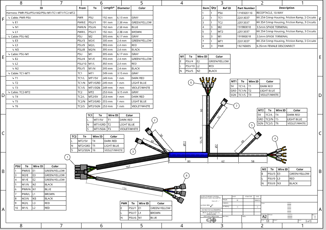
Currently what I achieved:
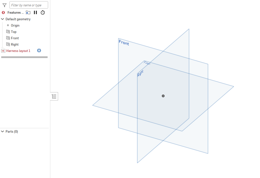 1
1 -
@Emily_Kwok "Currently what I achieved." 😂 I felt this deeply
3 -
@Emily_Kwok first thing is to make sure that the entire suite of features is at the latest version and your connector definitions have been updated (edit the feature and change a value to ensure that it is recalculated). Video is here:
Senior Director, Technical Services, EMEA0 -
Changelog for release 1.220.0
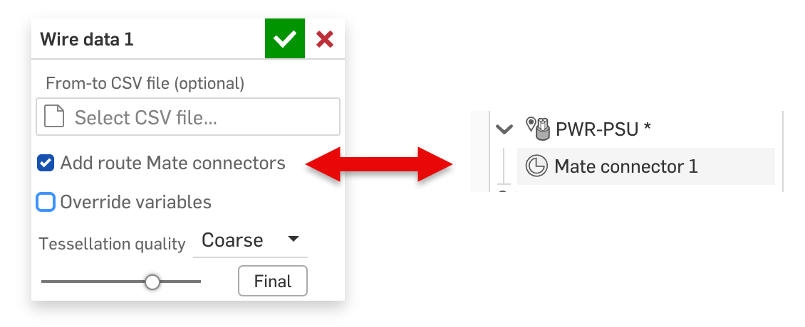
⭐️ Added Mate connector option for each route in the Wire data feature to make it easier to position individual wire routes in the top level assembly.
⭐️ Renamed Cable name field and moved it to the feature level to override Route name in all locations.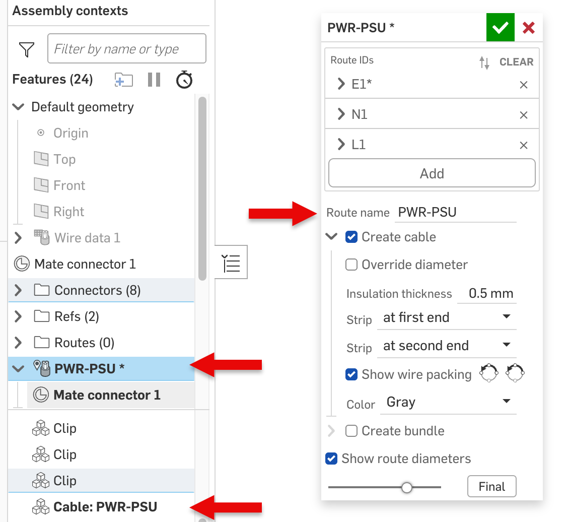
⭐️ Various bug fixes and performance improvementsSenior Director, Technical Services, EMEA3