Welcome to the Onshape forum! Ask questions and join in the discussions about everything Onshape.
First time visiting? Here are some places to start:- Looking for a certain topic? Check out the categories filter or use Search (upper right).
- Need support? Ask a question to our Community Support category.
- Please submit support tickets for bugs but you can request improvements in the Product Feedback category.
- Be respectful, on topic and if you see a problem, Flag it.
If you would like to contact our Community Manager personally, feel free to send a private message or an email.
Why does this extrusion fail?
 øyvind_kaurstad
Member Posts: 234 ✭✭✭
Hi,
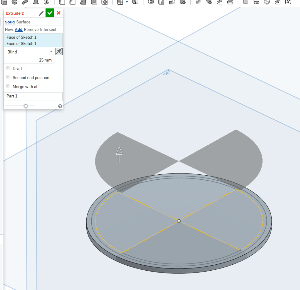
This is probably a silly question, but I'm asking anyway. Why does this extrusion fail?

If I try to extrude just one of the quadrants, no issues. However, extruding two diagonal quadrants fails. I guess it might have something to do with the center point, to which both are connected, but I fail to understand why this causes a failure.
This is probably a silly question, but I'm asking anyway. Why does this extrusion fail?

If I try to extrude just one of the quadrants, no issues. However, extruding two diagonal quadrants fails. I guess it might have something to do with the center point, to which both are connected, but I fail to understand why this causes a failure.
0
Best Answers
-
 andrew_troup
Member, Mentor Posts: 1,585 ✭✭✭✭✭
It makes no difference whatsoever to the mathematics engine whether zero thickness geometry is added to an existing solid or created from scratch:
even the tiniest amount of it, anywhere, is a show stopper because (currently) the solver cannot solve for this region.
You cannot have more (or less) than two faces of a single solid sharing a single edge, for one thing.
No matter how short that edge is. In the example given, you have four faces sharing an edge.
If you want the result shown, you will have to do it as separate bodies which are never merged.6 -
 lougallo
Member, Moderator, Onshape Employees, Developers, csevp, pcbaevp Posts: 2,016
  It's called non-manifold.Lou Gallo / PD/UX - Support - Community / Onshape, Inc.5
Answers
You can perform a search on the forums here with the term "zero thickness" to see others running into this as well.
http://www.ddicad.com/blogs/techcenter/2012/12/04/zero-thickness-geometry-explained/
It's easy enough to avoid in simple models, but can be troublesome in complex ones.
What's really tricky, though, is this one, in drawings of complex items,. such as stripper plates of multiple punch tooling, with lots of counterbored holes:
- The model could not be properly sectioned by the section line. Please check that the section line cuts through the model.
This can cause existing drawings to fail when a tiny edit is done to a model, which is particularly gallingIf Onshape can find a way to avert this siuation in section views in drawings, they will make a lot of tool designers very happy.
However, it is of course possible to work around this in several ways, it is just that I still feel it should be possible to extrude as one part in my example.
@jakeramsley @lougallo what do you think?
even the tiniest amount of it, anywhere, is a show stopper because (currently) the solver cannot solve for this region.
You cannot have more (or less) than two faces of a single solid sharing a single edge, for one thing.
No matter how short that edge is. In the example given, you have four faces sharing an edge.
If you want the result shown, you will have to do it as separate bodies which are never merged.
Maybe these are helpful...
http://www.transmagic.com/blog/19-what-is-non-manifold-and-manifold-geometry
http://doc.spatial.com/articles/m/a/n/Manifold_and_Non-manifold_Objects_2264.html
Thanks for those links, @pete_yodis
The first glosses over a few exceptions, when it says
Two well known exceptions where non-manifold geometry is regularly manufactured are coil springs (when spring-bound), and sheet-metal hems.
But a third exception is perhaps of more general interest.
If you bore a hole through a block of material, with the centre of the bore situated one hole radius from a face of the block, you get an infinitely thin edge which most definitely can be manufactured.
Obviously it is not usually done for practical reasons, but the exception is important in relation to section views in Drawings. I touched on this above, in
https://forum.onshape.com/discussion/comment/13202/#Comment_13202
But to those unfamiliar with tool design, it may be worth fleshing out the problem.
I'm thinking primarily of punch tooling setups like this (and this one is not particularly complicated, in comparison with some):
In this and other case containing multiple holes, each with multiple diameters, particularly where those diameters -- and the hole positions -- conform to a granular dimensioning scheme (or preferred numbers), it can be almost impossibly hard to find a section plane to produce a drawing view such as the one at right (passing through the centres of representative punches) which does not cause the modelling kernel to spit the dummy due to zero thickness geometry.
The drawing section view is limited by the same rules as part creation, and this is problematic.
In packages like Onshape which do not permit non-manifold solids, this is (in my experience) the most difficult implication to work around, and if Onshape + Seibert were to solve this, it would be a great boon to tool designers, among others.