Welcome to the Onshape forum! Ask questions and join in the discussions about everything Onshape.
First time visiting? Here are some places to start:- Looking for a certain topic? Check out the categories filter or use Search (upper right).
- Need support? Ask a question to our Community Support category.
- Please submit support tickets for bugs but you can request improvements in the Product Feedback category.
- Be respectful, on topic and if you see a problem, Flag it.
If you would like to contact our Community Manager personally, feel free to send a private message or an email.
Dealing with subassemblies in an assembly
 dave_franchino
Member Posts: 76 ✭✭
Hey folks, I'm struggling to deal with subassemblies effectively. I used a part studio to create the multiple parts that make up my design but they are intended to be assembled into a number of subassemblies which are then in turn assembled into my final main assembly. This feels like assembly 101 to me. But I have two issues I don't understand.
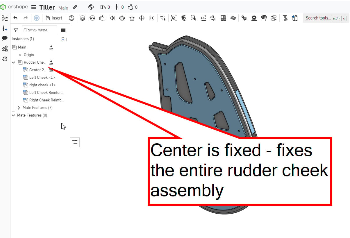
A) is a minor annoyance. When I insert my first Assembly into my main assembly, I learned through trial and error that if I "fix" any one part in that subassembly it in turn fixes the entire subassembly. While this works, it feels odd that I can't "fix" the subassembly in the model tree but only a part in that subassembly. Am I missing something? This isn't my primary issue though...


 My primary difficulty comes when I try to insert my next subassembly and mate it to this subassembly.
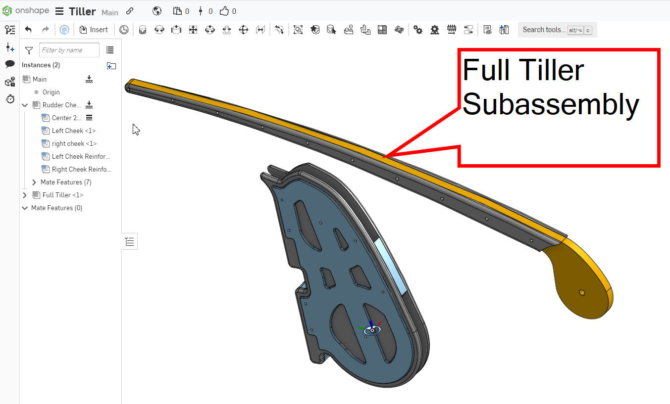
When I insert the new subassembly, even though it is fully constrained within it's own assembly, it comes in unconstrained in the main assembly.

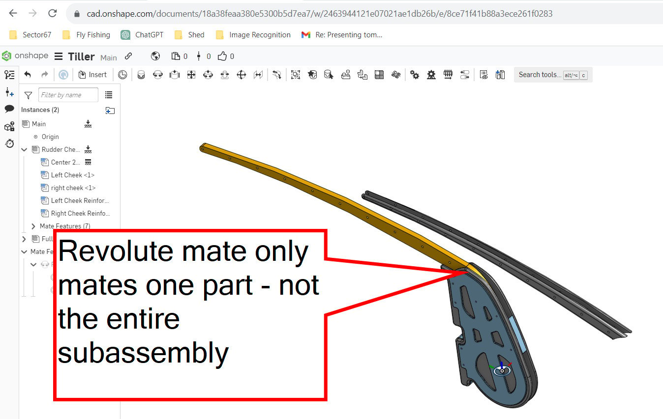
So when I try to mate this new subassembly to the other subassembly, it only moves one part - not the entire subassembly


There has to be a fix for this short of re-assembling the entire subassembly in each assembly it's used in.
Any advice?

A) is a minor annoyance. When I insert my first Assembly into my main assembly, I learned through trial and error that if I "fix" any one part in that subassembly it in turn fixes the entire subassembly. While this works, it feels odd that I can't "fix" the subassembly in the model tree but only a part in that subassembly. Am I missing something? This isn't my primary issue though...


When I insert the new subassembly, even though it is fully constrained within it's own assembly, it comes in unconstrained in the main assembly.

So when I try to mate this new subassembly to the other subassembly, it only moves one part - not the entire subassembly


There has to be a fix for this short of re-assembling the entire subassembly in each assembly it's used in.
Any advice?

0
Answers
Most likely your subassembly is overdefined with multiple fix "constraints" which does not effect higher level assemblies or has degrees of freedom which allows the parts to move. Grouping parts removes this freedom.
I understand this and I understand the group command. I can't understand why when one assembles a subassembly into another subassembly why the parts aren't automatically grouped!!! Isn't that the primary function of any assembly?? This is the way that Solidworks and other cad systems I've worked with work. I know the people who designed Onshape aren't dumb so there must be some logical reason why when you assemble an assembly into another it isn't inserted with those parts in fixed relationship to one another. But it doesn't make any sense to me and leads to all sorts of ugly work arounds.
For what it's worth, it would be cool if when you assembled an assembly into another there was an option to bring in that assembly grouped - that would have made more sense to me than to force someone to assemble an assembly and then immediately have to group it so it behaves like a single unit.
For that matter, the absence of planes in an assembly (and the inability to access the subassembly model trees) in Onshape also drives me crazy. I'm constantly struggling with assembling parts and subassemblies because of this. I have countless times where I need to create a "fake" cube and assemble it into my main assembly just so I have some orthogonal planes to work off of. Again - maybe I'm missing something here.
Again, I know I'm a victim of my previous experience and I'm trying to un-learn my previous workflows but these are things that make Onshape really frustrating until I can better understand how they wanted this to be handled!
Dave
If "Fix" is not a mate, how do you "start" assembling??? Unless I'm missing something (which I probably am) I don't have access to any planes in an assembly - just the origin. That's fine if I want to assemble something to the origin but there are plenty of times I don't want to do that.
Simon Gatrall | Product Development Specialist | Open For Work
I wasn't convinced at first either (also came from SW) but the assembly environment in Onshape is actually nicer to work with. It's a lot cleaner without all the extra crap in the tree. While there is the occasional time where it would be useful to access the "part level stuff" in assemblies, most of the time it just gets in the way and when I go back to SW I find myself endlessly scrolling around the tree looking for the stuff that actually matters.
The key is to get comfortable with working with mate connectors (i.e. creating explicit ones and also editing implicit ones), the only thing I dislike in this area is sometimes having to create a mate "wrong" in order to be able to edit the mate connectors after the fact... If we could edit the individual mate connectors directly from the mate dialogue it would really streamline things (as described here: https://forum.onshape.com/discussion/16715/add-option-to-edit-mate-connectors-from-the-mate-dialogue). Here's a discussion of the "finer points" of mate connectors that I didn't find were adequately covered in the training.
There is the odd case where the mate connector system can be slightly less "natural" but in the vast majority of cases it's superior (a lot easier to fix mating errors when you don't have multiple mates between the same part fighting each other!)
Having degrees of freedom translate upwards in the assembly structure is actually really nice and opens up a lot of things, as @S1mon put it, all assemblies are "flexible" in Onshape and I would argue it's not "natural" for a sub-assembly to become "frozen" when you insert it into a higher level (I believe the main reason SW behaves that way is for performance reasons, and the "flexible" option was added later to help get around that limitation...)!
All you need to do is ensure is all the parts in your sub-assembly are fully constrained relative to each other (i.e not by "fixing") if nothing needs to move a single group relation is all that is needed and then you just need one relation in the higher level to constrain everything I'm not seeing what "ugly workarounds" you are talking about...
Also note that if you have a sub-assembly that has some degree of freedom, you can still control it from a higher level with named positions, configurations (in the sub-assy) or adding a top level mate. The key is to not constrain more than necessary so if you have a revolute mate in the sub-assembly, you can add a cylindrical mate with rotation limits to further constrain it in the top level. Overall it provides a lot more "flexibility" in the way you can structure an assembly to represent "real world" than when the sub-assemblies become rigid by default!
In other words, if I create a mate connector at the origin it orients the Z axis facing upwards. I have the option to flip it so the Z axis is pointing downwards but what if I want the X axis to be the vertical axis? I'm sure there's an easy way to do this but I can't figure it out. Above someone mentions using the shift key but what does this do? On my computer pressing the shift key in the middle of this doesn't seem to do anything. What am I missing?
Thanks!
Holding the shift key once you are over the origin when creating a mate connector keeps you "locked" to that point making it much easier to pick the Z orientation (watch for the "up arrow" below my cursor when I hold shift and notice how the origin stays in focus as I move the mouse away from it):
Holding the shift key in general when selecting any implicit mate connectors will lock the entity you are over making it easier to pick the item you want. Trying to pick these center mate connectors can be very difficult without using shift.
I was aware of the ability to use rotate but unless I'm mistaken you're only allowed one "rotate" for a mate connector. I'm working on a sailboat rudder where the sailboat transom that the rudder is mounted to is angled at 5 degrees. It's a lot simpler to design the rudder at zero degrees (orthogonal) and then assemble it to the boat at 5 degrees but when I create a mate connector on the rudder the z axis is pointing along a different direction than the mate connector created at the origin. I just want to be able to specify which axis on the mate connector is pointed up.
I can work around this but it's just a bit frustrating and cobbled so I was hoping there was a clean approach I was missing.
I want to be clear I'm not whining about onshape. There's plenty to like but I just have some things to learn to make my modeling smoother
How do you "pick" the z axis origination?? That's the missing magic I'm not sure how to do!!!
Dave
If you are using the origin in an assembly you can move your mouse to make it point in one of the three front/right/top directions On anything else (including the origin of a part studio), you have to edit the mate connector and use the "realign"/"move" options.
If creating a mate, you have to create the mate first before you can go back and edit the mate connector. There some examples of that here:
https://cad.onshape.com/documents/8932a4a3d3645f4d7839a3fd/w/98826c63ff7862ce2db475d1/e/f58b23ce623e36ef83aadd62
Is there a training module that explains the "recommended" method of dealing with subassemblies? I keep thinking I've got assemblies figured out, only to have mates and group begin behaving strangely. Then I read forum topics like this and get confused all over again. It's driving me crazy and it seems like the assembly "system" was designed to be used in a way that is not adequately explained anywhere.
Hello @Adam_Reed_Erickson . Small world.
There are a couple things that are a bit different from Solidworks that made my initial experiences with Onshape assemblies maddening. They now mostly seem good, but different.
Feel free to ping me separately - we should catch up…
Simon Gatrall | Product Development Specialist | Open For Work