Welcome to the Onshape forum! Ask questions and join in the discussions about everything Onshape.
First time visiting? Here are some places to start:- Looking for a certain topic? Check out the categories filter or use Search (upper right).
- Need support? Ask a question to our Community Support category.
- Please submit support tickets for bugs but you can request improvements in the Product Feedback category.
- Be respectful, on topic and if you see a problem, Flag it.
If you would like to contact our Community Manager personally, feel free to send a private message or an email.
How to achieve parametric- or feedback friendly design using frames
 jan_vil
Member Posts: 9 ✭
jan_vil
Member Posts: 9 ✭
- Is it possible to somehow assign a variable to a frame profile, so when I need to change frame profiles of multiple frames, i could do it in one place not change every frame object separately?
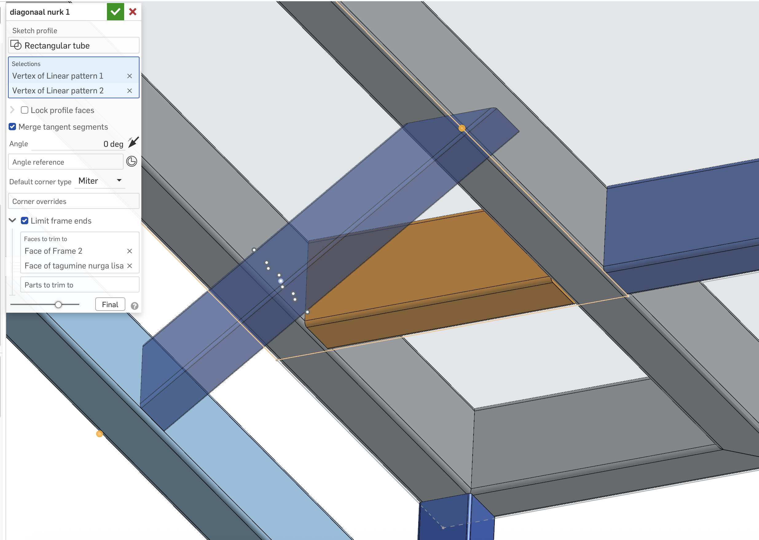
2. Regarding limiting frame ends. If i change the frame profile I have to re do most of the 'limit frame ends'. Whats the best way of automating this, so that if a frame profile is changed, the other frames would adapt automatically?
3. When using frames, what's the best practice in taking account profile sizes - ie I have a critical dimension where a width of 2 frames needs to be X. Now when I change the frame profile, I would like the sketches to adapt automatically. Is the best way creating a measured variable of the frame and using that variable in the sketch dimensions?
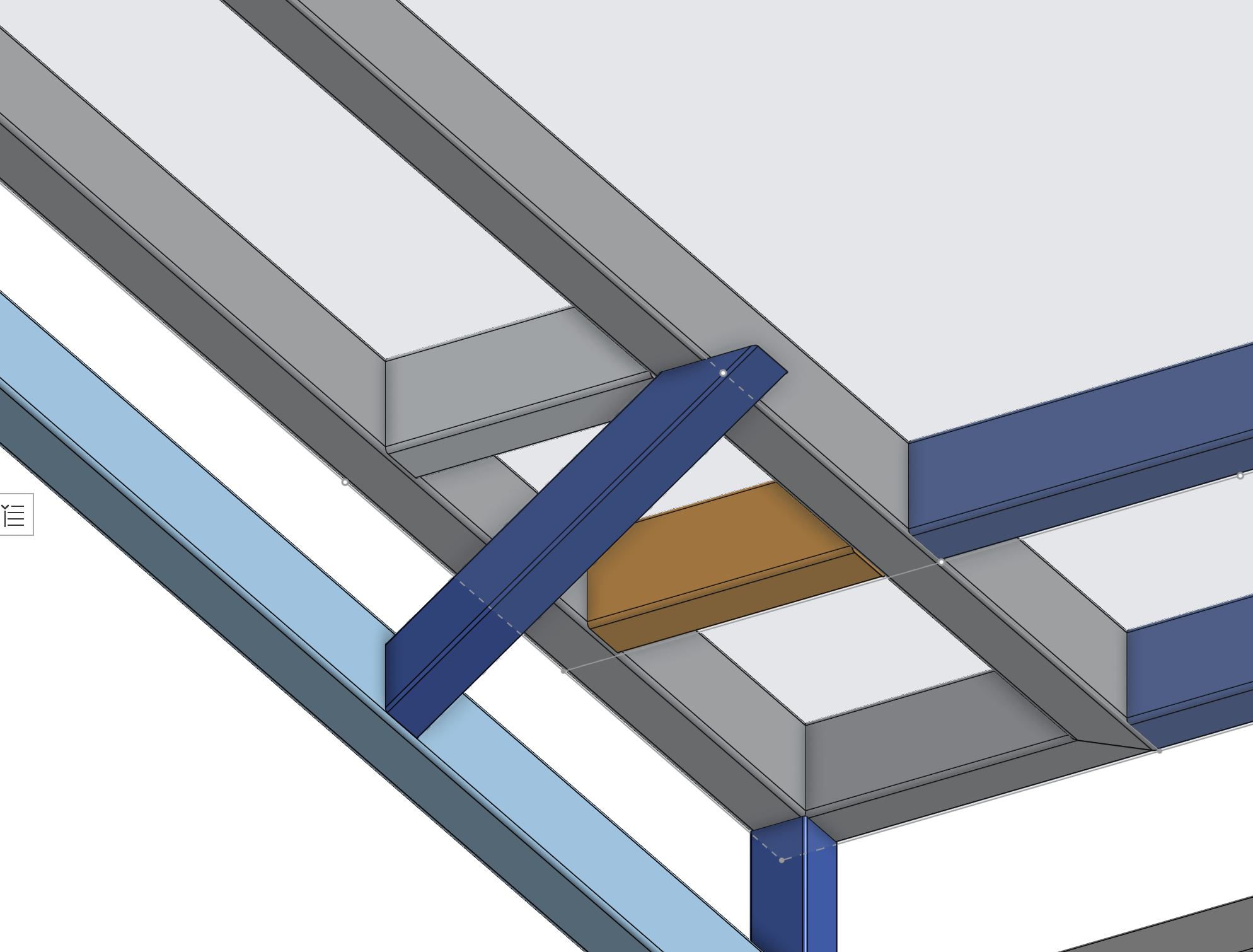
4. When using frames, I can adjust where the frame is situated along the points (not sure how to call this gizmo, pictured below.. How could I choose different points for both frame ends, so I could limit the diagonal parts upper end to the frame (the overall angle needs to change as well). Ideally I would like to avoid making new points to the sketch and doing it manually, since changing the profile later means I have to re do this.
Thank you in advance!
Answers
Hey @jan_vil!
.
.
.
Another way to do frames which is more robust for assemblies, is to have a single configured frame part studio where the profile is set up how i mentioned so that down stream references don't break. From there you can configure it to have different angles on the ends as well as a configured over-all length. What this does is allows you to change profiles of your frame in the assembly, while maintaining all downstream references. This way takes longer to set up, but is very clean and robust in the end.
RENDERCAD
rendercad.ai - Photorealistic product rendering.
▚▞▚▞▚▞▚▞▚
________________________________________________________________________
One thing I do miss about Solidworks is their implementation of the Structural System feature which allows you to define whole structural frames in their entirety in almost a single feature without having to do many single instances of frames / weldments. The global control possible with that tool was super nice. Frames in Onshape work a little weird at the moment in that they don't save information about their seed geometry in a way that can be reused (like sheet metal does) which makes implementing certain frame features a little difficult. I do have a prototype version of the frame tools that lets you select groups of faces or edges and evaluate them in order to handle branch cases that the tool doesn't currently support but it's got a long way to go before it's polished.
Derek Van Allen | Engineering Consultant | Meddler@Derek_Van_Allen_BD
I never used any other CAD system besides Onshape for Frames, but one of the things that prevents me from using a single Frame feature for my current project is that there's no way to individually set the locator points (defaults to 9 points) for each of the paths. Frame also won't handle certain topologies. I'd like to do more with a single Frame feature for a bunch of reasons.
I just created this improvement request because I couldn't find anything like it:
https://forum.onshape.com/discussion/28498/allow-frames-to-select-locator-points-per-frame-part
Simon Gatrall | Product Development, Engineering, Design, Onshape | Ex- IDEO, PCH, Unagi, Carbon | LinkedIn
You can add locator points while making a tag feature.
The only way I know for adding to existing frame tag is to make a fame from existing and copy the end profile with new points added.
@glen_dewsbury
I've made a custom frame profile for one project and figured out how to add the tags. That's not the problem I was discussing.
The issue I'm having is that this frame took multiple Frame features because I couldn't choose different points for different frame elements. Also the topology drove me to need more Frame features than I would have liked. In a few areas I could get several frame parts in one feature (see highlighted feature), but overall it was awkward. I suppose if I had started the reference sketches to all be on the center of the tubes it would have cut down on the complexity. But I wanted to reference corners which don't always work out neatly to be the same for all the elements.
Simon Gatrall | Product Development, Engineering, Design, Onshape | Ex- IDEO, PCH, Unagi, Carbon | LinkedIn
@S1mon I've got a number of projects I'm juggling right now where all the frame bodies are defined by edges or faces of solids and I'm currently getting around the cornering problem by moving faces in by half a frame width but that's not gonna be stable if I decide to change the frame standards at any point. All of these things are reasons I'm weighing a refactoring of the frames tool but to do it the way I'd really like I would need the ability to make a separate tab for the surface body definitions required to implement "simultaneous frames" like was done for sheet metal. That would definitely require some prerequisites to be met by the internal dev team at Onshape though.
Derek Van Allen | Engineering Consultant | MeddlerI have a variable for the frame size, and the frame is square tubing, so I could have done some stuff with 1/2 the frame size, but I didn't really consider that until I had gone down this path. If/when I do a lot more frames, I'll certainly plan things out a little differently.
I'd also like to see some more flexibility with the frames feature, like the IR that I shared. I could also see things where a reference could be two points so I don't need to add 3D Fit Splines or Sketches or Routing Curves to add elements between some existing points/verticies.
I'm sure that people that use Frames all the time have more wishes.
Simon Gatrall | Product Development, Engineering, Design, Onshape | Ex- IDEO, PCH, Unagi, Carbon | LinkedIn
@S1mon This explanation made the problem clearer. I have run into the same sorts of things so I voted for your IR.
This is a great feature request. That feature would've saved me heaps of time. Another good thing would be to have the same feature on patterns as well.
Thanks for your answer, much appreciated!
Could you please elaborate on point 4, and also the last paragraph.
@jan_vil Sure thing:
.
https://cad.onshape.com/documents/54a282082cc9d4a71c9e0ad2/w/0a6c3ceaeca20d5a45455e36/e/5f867d5183ccd04bb43…
.
https://cad.onshape.com/documents/54a282082cc9d4a71c9e0ad2/w/0a6c3ceaeca20d5a45455e36/e/718f3f8ad8f733535…
RENDERCAD
rendercad.ai - Photorealistic product rendering.
▚▞▚▞▚▞▚▞▚
________________________________________________________________________