Welcome to the Onshape forum! Ask questions and join in the discussions about everything Onshape.
First time visiting? Here are some places to start:- Looking for a certain topic? Check out the categories filter or use Search (upper right).
- Need support? Ask a question to our Community Support category.
- Please submit support tickets for bugs but you can request improvements in the Product Feedback category.
- Be respectful, on topic and if you see a problem, Flag it.
If you would like to contact our Community Manager personally, feel free to send a private message or an email.
Best approach for complex surface shape - Loft/Sweep/Bridging Curve/ other?
 jerome_stancil
Member Posts: 5 ✭
jerome_stancil
Member Posts: 5 ✭
Hello,
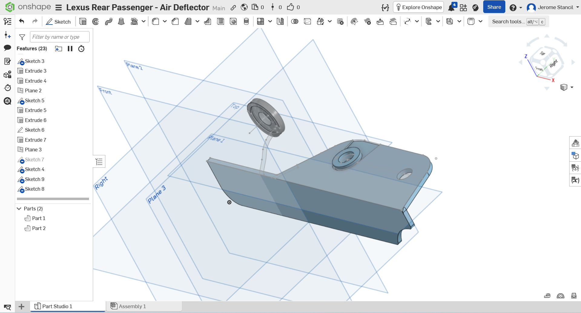
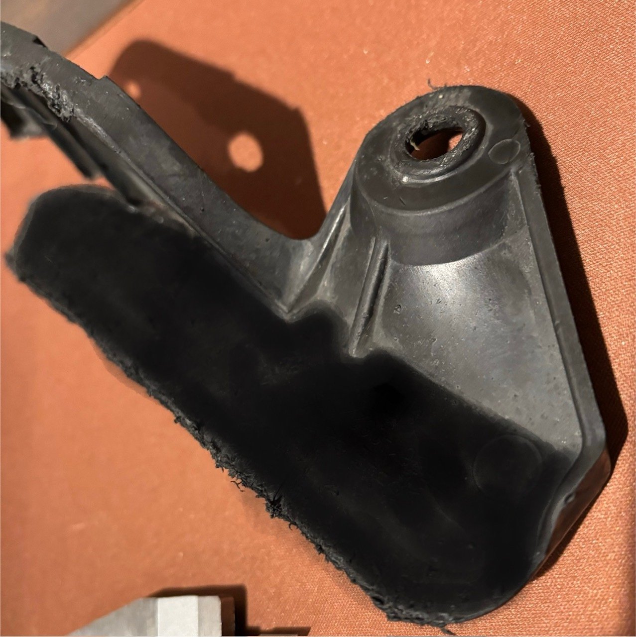
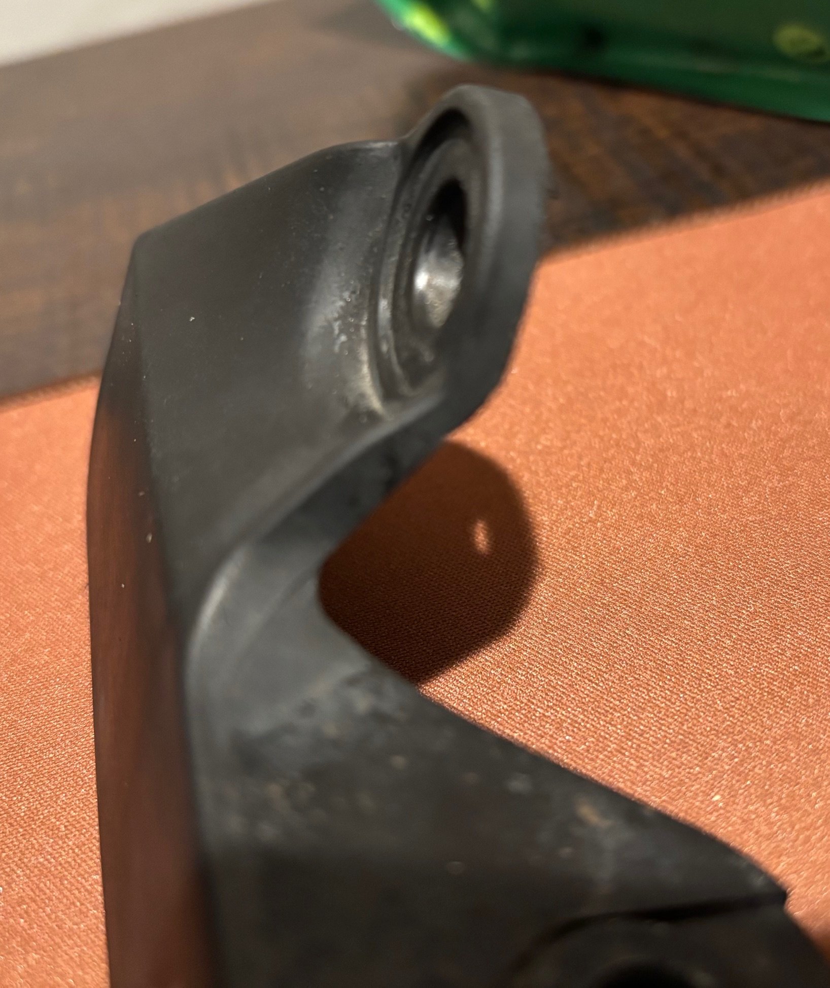
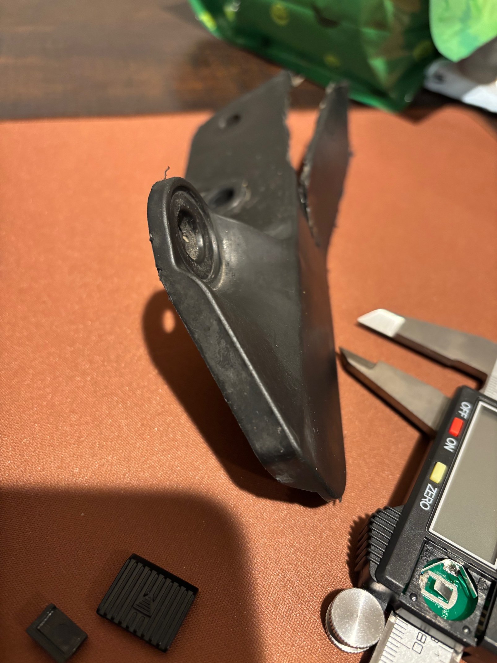
I am at my wits end, and am hoping someone can guide/help me along to finish my part design. I've included photos below of the part i am trying to model, and my current workspace state.
Workspace: https://cad.onshape.com/documents/d0d0b9f0b35e50dcff368c2b/w/8317e149768ed01810947d9b/e/2cdfec10e6bf54511fdc0afa?renderMode=0&uiState=692c6a03c3cf572209e5f172
I've tried loft (creates too much of a blocky piece, and i'm unsure of how to subtract the unwanted parts), path/revolve is too circular and has missing gaps, bridging curve + fill + enclose (unable to get bridging curve to take).
Really appreciate anyone taking the time to review, and any help offered.
Thank you!
Best Answer
-
 jelte_steur_info
Member Posts: 675 PRO
jelte_steur_info
Member Posts: 675 PRO
I think something along these lines is how the part is built up.
In general: please make sure sketches (like sketch 7) are fully constrained. the lack of tangency/concentricity etc is causing downstream issues quite quickly:
https://cad.onshape.com/documents/ccb37699191c84712fb79624/w/823c67f8bc41e015beb37e33/e/23b5ff33b5e667de837a2c931
Answers
This is a fairly complex set of features to model accurately. In general, you want to break down the shapes into surfaces with similar curvature and work from larger to smaller surfaces. It doesn't look like much in the more difficult area has a constant wall. You'll likely need to model the core and cavity sides somewhat independently.
I see a bigger transition surface, with some flanges on the sides that have some complex transitions at the ends. The core side has a conical surface coming off the round mounting feature, and then it has a large transition to the flat flange. The conical surface could be a partial revolve or semi-circular sweep. Next I would do some lofts or boundary surfaces for the major surfaces, and then work my way through the smaller more detailed bits.
Do you have multiples of this part that you could scrap one or two and cut some sections on a band saw? Can you do a 3D scan with an iOS device or a dedicated part scanner? Can you take some careful orthogonal photos with a really long lens to reduce parallax? Any of these methods would help give you more ground truth to start from. Calipers are only going to get you so far with shapes like these.
I noticed that a lot of your sketches are unconstrained. I would be careful with that, as you can easily end up with weird issues if you edit something early in the model and things aren't fully constrained or intentional.
Simon Gatrall | Product Development, Engineering, Design, Onshape | Ex- IDEO, PCH, Unagi, Carbon | LinkedIn
I think something along these lines is how the part is built up.
In general: please make sure sketches (like sketch 7) are fully constrained. the lack of tangency/concentricity etc is causing downstream issues quite quickly:
https://cad.onshape.com/documents/ccb37699191c84712fb79624/w/823c67f8bc41e015beb37e33/e/23b5ff33b5e667de837a2c93
@S1mon @jelte_steur_info
thank you both for the really good feedback. I was able to (after quite a bit more hours of work) a workable copy. However, I am going to review your sketch Jelte and see how you did it.
I am having issues understanding the sketches not being constrained. I was under the impression that once the shape snaps are used, and the sketch enclosed, or finished, it is constrained. I must be mis-understanding how to lock its contents in.
nonetheless, thank you both greatly!