Welcome to the Onshape forum! Ask questions and join in the discussions about everything Onshape.

First time visiting? Here are some places to start:
  1. Looking for a certain topic? Check out the categories filter or use Search (upper right).
  2. Need support? Ask a question to our Community Support category.
  3. Please submit support tickets for bugs but you can request improvements in the Product Feedback category.
  4. Be respectful, on topic and if you see a problem, Flag it.

If you would like to contact our Community Manager personally, feel free to send a private message or an email.

How do I align the center of a hole, with a line on a part that sits above it?

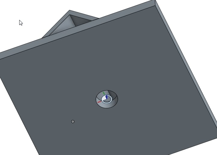
In SW I think I could easily create a coincident mate and select the axis of the hole and the line on the part above and it would align the two parts.  I'm learning more about onshape mates as I go along, but I can't seem to find a way to do this.  I have a mate connector created in the hole and the part above has two planar mates to align the top part to the top and side of the bottom part.  Now I only need to get it centered on the hole.
Tagged:

Best Answer

  • Tony_C_Tony_C_ Member Posts: 273 PRO
    Answer ✓
    Ok, I will try that.  I am pretty sure I tried this previously.  Maybe I just need more practice.  I agree, the change from SW Mates to OS Mates was difficult starting out, but I've been liking it after understanding it more and gaining experience.  The biggest complaint I can give at this point is that faces don't seem to "Pick up" when my cursor is very apparently hovering right over it!  I tend to have to zoom in qite a lot to get it to recognize I want it to select that face.

    Other than that I think you can generally mate things with fewer steps.
    @james_hulliberger you need to watch this video.

    https://www.onshape.com/videos/secrets-of-the-shift-key

Answers

  • NeilCookeNeilCooke Moderator, Onshape Employees Posts: 5,714
    Hi @james_hulliberger welcome to Onshape! You have fallen into the trap that most SW users fall into - you can do this with one mate. You should very rarely need to use planar mate at all, plus there is no need to create a mate connector. Select fasten mate (or slider/cylindrical if it needs to slide) and hover over the hole to get one mate connector, then hover over the line to get the other.

    Senior Director, Technical Services, EMEAI
  • james_hullibergerjames_hulliberger Member Posts: 14
    Ok, I will try that.  I am pretty sure I tried this previously.  Maybe I just need more practice.  I agree, the change from SW Mates to OS Mates was difficult starting out, but I've been liking it after understanding it more and gaining experience.  The biggest complaint I can give at this point is that faces don't seem to "Pick up" when my cursor is very apparently hovering right over it!  I tend to have to zoom in quite a lot to get it to recognize I want it to select that face.

    Other than that I think you can generally mate things with fewer steps.
  • james_hullibergerjames_hulliberger Member Posts: 14
    Doesn't do what I want.  The top part flips up vertically to align the DIRECTION of the line with the axis of the hole.  I just want the line along the center of the top part to center up with the center of the hole.
  • james_hullibergerjames_hulliberger Member Posts: 14
    The document is shared to support if someone wants to get a better look at it.  It might not be easy to see what I want from that image.  I'd like the cut out section of the square tube to be resting on the plate, with the square tube centered on the plate.
  • owen_sparksowen_sparks Member, Developers Posts: 2,660 PRO
    If it's not confidential then sharing it on the forum will open up the pool of folks able to help.

    Owen S.
    Business Systems and Configuration Controller
    HWM-Water Ltd
  • james_hullibergerjames_hulliberger Member Posts: 14
    Not confidential at all.  I didn't know about sharing with forum.  Hold on...
  • owen_sparksowen_sparks Member, Developers Posts: 2,660 PRO

    Sorry I should have been more specific; my comment's a bit misleading.   "Make doc public (with at least copy permission) and post hyperlink here" makes more sense.

    Owen S.
    Business Systems and Configuration Controller
    HWM-Water Ltd
  • owen_sparksowen_sparks Member, Developers Posts: 2,660 PRO
    Hi @james_hulliberger, close, just need to add edit or copy permission for us to be able to add anything to it.

    Cheers, Owen S
    Business Systems and Configuration Controller
    HWM-Water Ltd
  • james_hullibergerjames_hulliberger Member Posts: 14
    Yep.  I can't make those settings.  Those options are not available for some reason.  It's a public document.  I'm just designing a homebrew BIAB rig for making beer with.  If I can get an email address, I can try sharing with a specific person?
  • james_hullibergerjames_hulliberger Member Posts: 14
    By default it should be copyable since it's a free account...
  • owen_sparksowen_sparks Member, Developers Posts: 2,660 PRO
    edited April 2017
    Ah-ha, I see it's copyable now.

    How about this?

    https://cad.onshape.com/documents/58f8dea5f58534111bfa92a7/w/5c75d9dc5fd343dbcc92432f/e/1e7db1500c0c07eb82a53cd2

    I ended up adding a custom mate in the part studio for the pipe part and taking an infered one on the edge of the plate.

    There may be better ways, I'm just learning...

    Cheers,

    Owen S.
    Business Systems and Configuration Controller
    HWM-Water Ltd
  • owen_sparksowen_sparks Member, Developers Posts: 2,660 PRO
    Possibly worth noting that all this could be designed in place in one part studio, and would not need any mates at all.  BTW nice project!

    Owen S
    Business Systems and Configuration Controller
    HWM-Water Ltd
  • james_hullibergerjames_hulliberger Member Posts: 14
    OS says it failed to load the document.  Maybe something about rights to your link?

    Also, I agree this could be done in a single Part Studio, but I'm designing to use some very common materials to make the project buildable by the average person is they wish.  Just drawing up some different options for different steel products someone might have access too, hence the various versions using Sq Tube, Angle Iron, etc.
  • owen_sparksowen_sparks Member, Developers Posts: 2,660 PRO
    Sorry, my bad, I'd answered two topics and not made your reply public.  Please try the link again.

    Open source beer making?  Very nice sir.

    BTW if anyone else is reading this and you have a better method than please shout.

    Cheers,

    Owen S.
    Business Systems and Configuration Controller
    HWM-Water Ltd
  • james_hullibergerjames_hulliberger Member Posts: 14
    OK, well I had to study your work a bit to catch on, but I did get it emulated in my own document.  It's kind of several steps to get it set up before you use a single connector LOL!  But it does get the job done.

    Thank you.
  • Tony_C_Tony_C_ Member Posts: 273 PRO
    Answer ✓
    Ok, I will try that.  I am pretty sure I tried this previously.  Maybe I just need more practice.  I agree, the change from SW Mates to OS Mates was difficult starting out, but I've been liking it after understanding it more and gaining experience.  The biggest complaint I can give at this point is that faces don't seem to "Pick up" when my cursor is very apparently hovering right over it!  I tend to have to zoom in qite a lot to get it to recognize I want it to select that face.

    Other than that I think you can generally mate things with fewer steps.
    @james_hulliberger you need to watch this video.

    https://www.onshape.com/videos/secrets-of-the-shift-key
  • NeilCookeNeilCooke Moderator, Onshape Employees Posts: 5,714
    Senior Director, Technical Services, EMEAI
  • john_mcclaryjohn_mcclary Member, Developers Posts: 3,938 PRO
    Ah-ha, I see it's copyable now.

    How about this?

    https://cad.onshape.com/documents/58f8dea5f58534111bfa92a7/w/5c75d9dc5fd343dbcc92432f/e/1e7db1500c0c07eb82a53cd2

    I ended up adding a custom mate in the part studio for the pipe part and taking an infered one on the edge of the plate.

    There may be better ways, I'm just learning...

    Cheers,

    Owen S.
    You're right, this would be best in a single part studio to utilize the most powerful mate of them all.. "group"
    But if that is not what you want. Then You did my next favorite method @owen_sparks, add a mate connector in the part studio.

    @NeilCooke I considered this as well, but I try to keep it as a rule of thumb, never to have a manually entered dimension in an assembly if at all possible. (especially if it's something you want "on center")
    It's just one more place to update when there is a change. (not a big deal in such a small assembly, but just trying to build good habits)

    Just some more food for thought...
  • owen_sparksowen_sparks Member, Developers Posts: 2,660 PRO
    edited April 2017
    @john_mcclary Agreed, the mate connector in the Studio method seems clean and robust, and in the example above keeps the design intent by using a sketch with projected mid-point. 

    I sometimes use PartStudio Mates even on points that can be infered in the assy.  Less zooming required and no chance of picking the wrong point on holes for example that may have top, bottom and mid points very close togeter. 

    I'm also hoping that when @ilya_baran is done with FeatureScript then he'll move on to AssemblyScript :)

    I really like the idea of having a process where we can have a scripted assembly method something like this:-

    CreateAssembly("MyProduct")
    ImportPart("Case")
    Transform(Case.mate1,origin)
    ImportPart("InputConnector")
    ImportPart("OutputConnector")
    Mate(Case.mate2,InputConnector.mate1)
    Mate(Case.mate3,OututConnector.mate1)

    Then perhaps...
    Render("MyProduct", ExportAsJPG=True, "C:\TempProductImage.jpg)
    Delete(MyProduct)

    Owen S.
    Business Systems and Configuration Controller
    HWM-Water Ltd
  • NeilCookeNeilCooke Moderator, Onshape Employees Posts: 5,714
    @john_mcclary my example has no dimensions but the cylindrical mate is reliant on the other end of the tube not changing which cannot be guaranteed. I agree a mate connector in the part is the best option. Actually, modelling it all together in a Part Studio is the best option  ;)
    Senior Director, Technical Services, EMEAI
Sign In or Register to comment.