Welcome to the Onshape forum! Ask questions and join in the discussions about everything Onshape.
First time visiting? Here are some places to start:- Looking for a certain topic? Check out the categories filter or use Search (upper right).
- Need support? Ask a question to our Community Support category.
- Please submit support tickets for bugs but you can request improvements in the Product Feedback category.
- Be respectful, on topic and if you see a problem, Flag it.
If you would like to contact our Community Manager personally, feel free to send a private message or an email.
Countersink Screws and Holes Mating
 DarK_AlximiK
Member Posts: 11 ✭
Hi
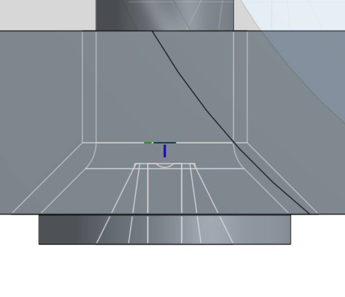
Countersink screws has a mating snap point right after fillet before tapping starts is making problem during automatic countersink hole population.
You can see that mated part is not flat to the countersink surface

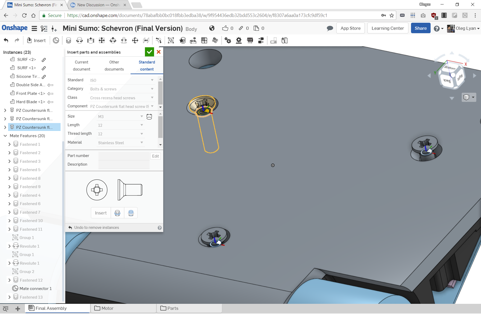
Example bellow is overall view

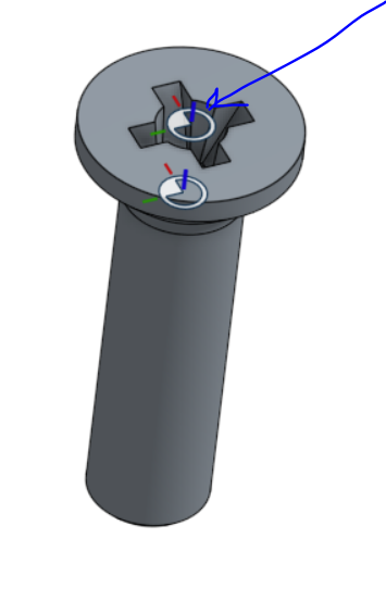
I would suggest to add possible mating point for imaginary top of the cone inside the part or the center of the bolt hat should be made as mating point

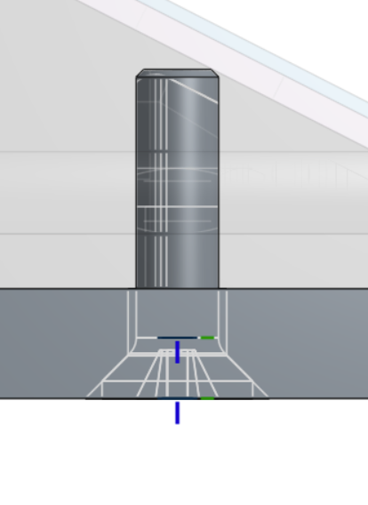
Then it is almost perfectly mated, would be nice to have mated tops of the cones

Countersink screws has a mating snap point right after fillet before tapping starts is making problem during automatic countersink hole population.
You can see that mated part is not flat to the countersink surface

Example bellow is overall view

I would suggest to add possible mating point for imaginary top of the cone inside the part or the center of the bolt hat should be made as mating point

Then it is almost perfectly mated, would be nice to have mated tops of the cones

Tagged:
3
Comments
The most important part about properly mating countersunk fasteners is ensuring that the conical surfaces match up. Mating to the planar surface of your part might look good for for CAD (and may match the conical surfaces up by chance), but upon manufacturing and assembly you will find the tolerance of your holes and the tolerance of the fasteners themselves stacking. The end result will be you, in final assembly and QA, running your hand over your part all to find fasteners inconsistently sticking above and below the planar surface of the part.
To properly DFM and DFA your holes to accommodate countersunk fasteners, there should be counterbored recess below the surface or a slightly over-countersunk hole in your part. This will ensure that your fasteners do not stick above the surface of the part. This z offset to the fastener is up to the designer and is specific to the fastener.
The best Mate Connector point would be the point of the projected conical surface, on both the hole and the fastener. This would ensure proper fitment of the fastener to the hole and accurate recess information. Our hole feature, unfortunately, does not yet fully support inserting holes for standard content or inserting holes designed for specific fasteners. We already planned on covering this case, but I will write up this as a customer improvement request and attach it to our hole feature. Please look for improvements to our hole feature in the future.
Thanks!
Jason
That is the design intent of flat heads; and allows you to select a face with many holes and insert with one click with replicate or standard content insert.
Those skilled in the trade of machining / manufacturing will (should) be setting c'sink depth with a screw in hand, and make deeper cuts if necessary to match specifications on the drawing.
measuring from the fillet on a fastener (which is CAD glamour that could be removed IMHO) to the bottom of a chamfered hole, changes the offset based on the hole diameter.
If it wasn't obvious, below is the same hole with hole feature, I did a move face to make the right hole larger diameter slightly.
Any mate that needs to be manually offset, should only be done as a last resort IMHO. Similar to distance mates in other parametric cad. Avoid if at all possible.
So if any change is to happen, please consider top of flat head. Whether or not the bolt seats into the plate in CAD is too much calculation for little payback.
Unless you are 3D printing, at which point you would be examining more closely and should be adjusting your cut hole, not your mate.
HWM-Water Ltd
No CAD model of a fastener should be trusted as 100% accurate. Not even the fasteners are consistent between batches / brands. Field fit is part of the trade. So CAD should treat the c'sink as such and only show the c'sink for cosmetic / callout.
Whether or not the fastener sits in the perfect tangent to the c'sink in the model is irrelevant.
For example, I just went to the shop and gabbed a 1/4-20 FHCS, here is the difference between CAD and Reality:
The blue is measured with calipers, the gray is Onshape content, the c'sink hole is the same...
If we "Trust" CAD to the level of detail as countersinks.. then the blue bolt would be .02" below the surface, assuming he sharpened his drill bit correct, and the hole didn't become oversize from a wobbly bit. (yes it does make the fastener sit deeper even if the c'sink is the same depth)
CAD should show intent (which is flush with top 99% of the time) only specific cases where you are using (for lack of a better example off the top of my head) a flat head screw as a makeshift dovetail or something. where you would have it above the surface by a little bit to act like a catch. But that would be specific and rare that it would be acceptable to create a custom offset or mate in those cases.
Design standard content to be standard for the majority of the time. In 14 years in the trade. Flat heads have almost always been flush with the top, fit at machining/assembly, with a small handful of exceptions that are so rare that I know it has happend... but I can't remember when or why without really looking back at old projects.
Today flat head mate is completely useless to me and I re-mate to the top of the head and curse Onshape every time.
There are too many variables to consider with flat heads. Which is why we ignore collision errors in the model and show design intent on the drawing and to the shop.
HWM-Water Ltd
Where there is an issue with burrs, I would use socket head screws and tighten them with a torque-limited screwdriver. Socket heads seem to deform less than cross-point screws.
Apparently it's everyone else here that's crazy, so I guess I'm the minority... Y'all can do whatever works good for you, and I'll do what I've been doing without any issues for years is SolidWorks. I'm done caring at this point. Not worth stressing over
By the way, I work in the railway industry, and I agree on the fact that proper mating should be with conical surfaces. It's just not possible to adapt the machining in our case, as all parts comes from different suppliers. Screws are manufactures to a standard, and we design the holes to match this in all allowed tolerances of the standard.
What you are really doing is mating the points of two cones of the same size, so they end up being flush with the c'sink.
Improvements to Onshape - June 18th, 2019 — Onshape