Welcome to the Onshape forum! Ask questions and join in the discussions about everything Onshape.

First time visiting? Here are some places to start:
  1. Looking for a certain topic? Check out the categories filter or use Search (upper right).
  2. Need support? Ask a question to our Community Support category.
  3. Please submit support tickets for bugs but you can request improvements in the Product Feedback category.
  4. Be respectful, on topic and if you see a problem, Flag it.

If you would like to contact our Community Manager personally, feel free to send a private message or an email.

Options

Help translating process flow from Solidworks to Onshape for FRC team

derek_wardderek_ward Member Posts: 63 EDU
edited January 2018 in Community Support
Hello, I've been dabbling with Onshape for the past couple of years now and I definitely see the potential, and I've used it very successfully for many projects at my school, but I've been having a hard time converting the workflow that my FIRST Robotics Team uses currently in Solidworks.  

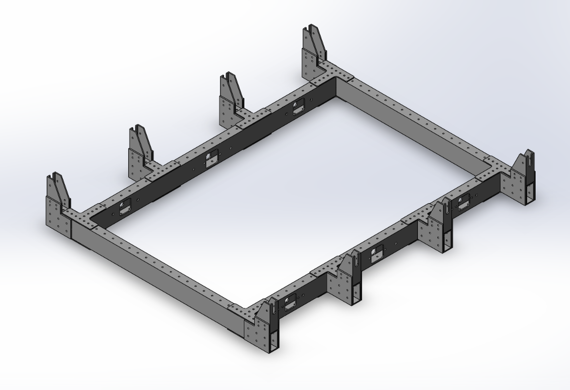
For example, to create our chassis we usually use a combination of aluminum 1" x 2" tubing, gussets, gearboxes and wheels from Vex Robotics.  We typically make our chassis in the West Coast Drive orientation (it looks like a Roman Numeral 2).  Below is a picture of our chassis
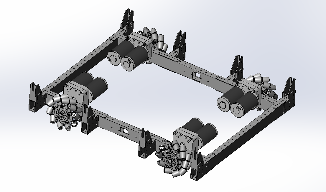


To make this we typically start with a layout sketch on paper and start to construct the individual 2x1 tubes and bring them into an assembly, mate them appropriatly, add gussets, bring in gearboxes and position them accordingly, edit the parts within the assembly, make the cuts and continue to build up the chassis assembly.  

I'm having trouble converting that process to Onshape because of the different paradigm that Onshape has and the fact that we need to deal with third-party parts and assemblies.  For example, I can easily create a chassis from tubing in Onshape, however, should I bring in the gussets via Derive into the Parts Studio, translate them to the proper position via mate connectors, or should it happen in an assembly?  Perhaps I need to explore in context modeling further?  Below is a link to our Solidworks model for the above chassis.  Any advice would be greatly appreciated.  

https://drive.google.com/drive/folders/1dh-LyxZRTGglD5rZHjf_tIFIOM1e9oQN?usp=sharing  

Here's a link to an Onshape document where I'm trying to recreate the chassis.
Tagged:

Answers

  • Options
    mahirmahir Member, Developers Posts: 1,291 ✭✭✭✭✭
    edited January 2018
    Generally, I use part studio to create unique parts. If those parts need to get repeated, then I will replicate them in an Assembly. So, if you're using the same parts many times, I'd go with an Assembly since that way you will get a performance improvement from OS's use of part instances. In a part studio, each part body is considered its own separate entity instead of a copied instance. That will tend to bog down performance. Plus, if you end up making a BOM, you'll want to use an Assembly.
  • Options
    noanoa Onshape Employees, Developers Posts: 141
    @derek_ward I agree with @mahir that assemblies are the best place to bring together 3rd party parts and you should only have one unique part in a part studio. One workflow I've seen work well is:

    1) In a part studio, create a layout sketch.
    2) Create a dummy part (i.e. a block in the center)
    3) Create mate connectors at key locations of your sketch (likely vertices at corners, etc.) with that dummy part as the "Owner part"
    4) In other part studios, use the derive feature to bring that sketch and its mate connectors in.
    5) Model new parts referencing that layout sketch (e.g. extrude from one end of a line to the vertex on the other side using the "up to vertex" end condition)
    6) Insert new these new parts into the assembly and make use of your pre-defined mate connectors for easy mating


    Here is a public document I whipped up to show how you can create such a layout sketch. https://cad.onshape.com/documents/7cf5926f1554396947c911ef/w/5d8e7ced7ddbdbeeb23619e3/e/3f9f49df5a5d6dcb26ab4888

    Editing in context is a powerful workflow and has its uses. You could even use it to achieve a similar thing as above without the use of the derive feature. It is most useful if you are trying to design around an assembly's range of motion, or if you need more than just some lines in a layout sketch to create geometry (e.g. a complex interface between two parts). You can learn how to use it here: https://learn.onshape.com/courses/managed-in-context-design

    Hopefully this gives you a good starting point!

    -Noa
    Noa Flaherty / Customer Success / Onshape Inc.
  • Options
    mahirmahir Member, Developers Posts: 1,291 ✭✭✭✭✭
    @noa, is that dummy part really necessary? Having the dummy there seems kind of klugy. Since you're only adding the mate connectors once anyway, may as well import just the layout sketches and add the layout mate connectors in the assembly and not the part studio. Or just create the MCs on the fly if the layout vertices provide a clear enough locating strategy (which in this case they do).
  • Options
    derek_wardderek_ward Member Posts: 63 EDU
    edited January 2018
    @mahir, @noa

    Thank you both so much for the suggestions!  I'm going to try them out. Also, @mohir, I think you need the dummy part since MCs need to be attached to a part, no?
  • Options
    mahirmahir Member, Developers Posts: 1,291 ✭✭✭✭✭
    Also, @mohir, I think you need the dummy part since MCs need to be attached to a part, no?

    @derek_ward, right. I know the reason for the dummy part. I just don't think having the MCs attached to the part is necessary enough to require the dummy part. I would just add the MCs to the layout sketch at the assembly level - either ahead of time or on the fly while creating mates.
  • Options
    brucebartlettbrucebartlett Member, OS Professional, Mentor, User Group Leader Posts: 2,137 PRO
    edited January 2018
    mahir said:
    Also, @mohir, I think you need the dummy part since MCs need to be attached to a part, no?

    @derek_ward, right. I know the reason for the dummy part. I just don't think having the MCs attached to the part is necessary enough to require the dummy part. I would just add the MCs to the layout sketch at the assembly level - either ahead of time or on the fly while creating mates.
    I could be wrong but I think @mahir is suggesting inserting the layout sketch into the assembly and mating the parts directly rather than mate connectors on a dummy part.  That way you don't have to add all the connectors on the dummy part just added them in the assy on the fly and means you don't an extra part hanging around in the assy to confuse things, I used to use dummy parts and mate connectors before insert sketch into assembly was available.
    Engineer ı Product Designer ı Onshape Consulting Partner
    Twitter: @onshapetricks  & @babart1977   
  • Options
    MBartlett21MBartlett21 Member, OS Professional, Developers Posts: 2,034 EDU
    @mahir, @noa

    Thank you both so much for the suggestions!  I'm going to try them out. Also, @mohir, I think you need the dummy part since MCs need to be attached to a part, no?
    @derek_ward


     If you would like to have mate connectors owned by sketches, there is an improvement request for it.

    https://forum.onshape.com/discussion/8162/mate-connectors-in-sketches
    mb - draftsman - also FS author: View FeatureScripts
    IR for AS/NZS 1100
  • Options
    noanoa Onshape Employees, Developers Posts: 141
    Yes, adding mate connectors to a dummy part and within the part studio (as opposed to directly within the assembly) may be unnecessary, but would be helpful if you planned on inserting that layout sketch into multiple assemblies (and you wanted each to have the mate connectors) or if you purposefully wanted the mate connectors when you derive the sketch into other part studios.

    If you wanted to keep things simple, doing as @mahir and @brucebartlett suggest is a good idea.
    Noa Flaherty / Customer Success / Onshape Inc.
  • Options
    philip_thomasphilip_thomas Member, Moderator, Onshape Employees, Developers Posts: 1,381
    YES _ PLEASE VOTE FOR MATE CONNECTORS OWNED BY SKETCHES - I WANT THIS !!!  :)  
    Philip Thomas - Onshape
  • Options
    owen_sparksowen_sparks Member, Developers Posts: 2,660 PRO
    Do you take more notice of our IR's if we type them in capitals?  :p:p

    OwS
    Business Systems and Configuration Controller
    HWM-Water Ltd
  • Options
    brucebartlettbrucebartlett Member, OS Professional, Mentor, User Group Leader Posts: 2,137 PRO
    On further reflection, I can see if you have a dummy model with mate connector as in @noa 's example you can have connector positioned in 3d space rather than just being limited to a flat plane.   @mbartlett21 's request for attaching mate connectors to a sketch would be a great option to get the best of both worlds as I imagine that the Mate Connectors could still be positioned anywhere in 3d space not just the sketch plane. 
    Engineer ı Product Designer ı Onshape Consulting Partner
    Twitter: @onshapetricks  & @babart1977   
  • Options
    kate_leipold_ritkate_leipold_rit Member Posts: 36 EDU
    YES _ PLEASE VOTE FOR MATE CONNECTORS OWNED BY SKETCHES - I WANT THIS !!!  :)  
    Done!
Sign In or Register to comment.