Welcome to the Onshape forum! Ask questions and join in the discussions about everything Onshape.
First time visiting? Here are some places to start:- Looking for a certain topic? Check out the categories filter or use Search (upper right).
- Need support? Ask a question to our Community Support category.
- Please submit support tickets for bugs but you can request improvements in the Product Feedback category.
- Be respectful, on topic and if you see a problem, Flag it.
If you would like to contact our Community Manager personally, feel free to send a private message or an email.
Configuration to Chose a Shape in a Sketch
 neobobkrause
Member Posts: 105 EDU
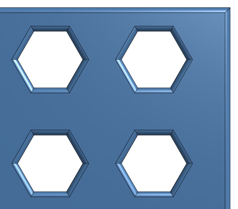
I have a shape that includes a surface with a pattern of holes. Sometimes I want the holes to be round, but other times I want them to be hex shaped, and so on. Prior to OnShape configurations showing up on our doorsteps, I've managed this set of variations using a sketch that included all the various hole patterns I might be interested in, but set all but the "current" pattern as Construction lines. Something like this...

In all that clutter, you'll notice that the only non-Construction element in the sketch is the hexagonal shape. Changing the hexagon to a Construction, then converting the circle, diamond, or smaller hexagon to be non-Construction will result in the shape having cutouts of those shapes.

My question is how/whether OnShape's new Configuration capabilities can be used to cleanly select the cutout shape of this object.
- Bob

In all that clutter, you'll notice that the only non-Construction element in the sketch is the hexagonal shape. Changing the hexagon to a Construction, then converting the circle, diamond, or smaller hexagon to be non-Construction will result in the shape having cutouts of those shapes.

My question is how/whether OnShape's new Configuration capabilities can be used to cleanly select the cutout shape of this object.
- Bob
Tagged:
0
Comments
https://cad.onshape.com/documents/57acdfaae4b005c413ed9b6f/w/3fd585a46d3af1b3ba413c53/e/b02ec721136c6121c1a02cc1
Simple method
(i) An initial sketch with just hole location vertices.
(ii) Individual sketches for each hole type, and select these using configs.
Nicer Method
Make a simple featurescript with a "Hole Shape" drop down list, and then configure that input.
This has the option that you can then use "created by" with an edge filter to add a chamfer to the hole.
Cheers,
Owen S.
HWM-Water Ltd
All you need to do is to add the selection list for the extrude to the configuration input, which will then display the selection count in the table. When you double click on this cell in the table you can change the selections to a different sketch, or you can add or remove regions from the selection list.
See this simple example of configured selections:
https://cad.onshape.com/documents/7e5e83e6885dae5776260b9a/w/2339a1a63af248955ab9d648/e/0d31f7998ae62e42f60df3ff
Andy
OwS
HWM-Water Ltd
I have tried a number of things, all with the same results.
Thanks
Could you post the URL of your document? Then we can take a look. Maybe these instructions will help:
https://cad.onshape.com/help/Content/configurations.htm
HWM-Water Ltd