Welcome to the Onshape forum! Ask questions and join in the discussions about everything Onshape.
First time visiting? Here are some places to start:- Looking for a certain topic? Check out the categories filter or use Search (upper right).
- Need support? Ask a question to our Community Support category.
- Please submit support tickets for bugs but you can request improvements in the Product Feedback category.
- Be respectful, on topic and if you see a problem, Flag it.
If you would like to contact our Community Manager personally, feel free to send a private message or an email.
Combining fillet and chamfer to facilitate 3D printing of part
 no_thanks454
Member Posts: 7 ✭
no_thanks454
Member Posts: 7 ✭
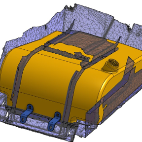
I have reverse-engineered a part that I'd like to 3D print. To make it look somewhat like the original, I want to have a fairly large (10mm radius) fillet on the edges of the bottom. The bottom will also be on the print bed. However, most FDM 3D printers cannot handle overhangs of more than 70 to 80 degrees. Therefore, I would like the bottom part of the fillet to be a 70 degree chamfer, until the angle of the fillet becomes less than 70 degrees and it can continue as a fillet.
I managed to get this partially working, but only with a tiny chamfer and tiny fillet:
How can I do this in a nice way with the large fillet? Thanks!
Answers
not sure what exactly you aren’t able to do but you can apply a fillet to a chamfer edge if that’s what your after
He doesn't want the fillet to end tangent with the base face (printbed). Instead he wants a small chamfer-like face to extent tangentially from the fillet at say 70° or whatever overhang angle his printer can do.
The issue is the main corner radius of 3mm. You need to make it much bigger if you want a larger chamfer and/or fillet to be able to wrap around it.
Precisely! In the part I linked, I have done precisely as suggested above, namely first created a 70-degree chamfer and then applied the fillet to the top edge of that. This works in the sense that I could now print it. But I would like to have a nice big round-over (like a 10 mm radius big) and the chamfer doesn't generate if I make it bigger than 1mm:
So I guess my question is: how can I make this chamfer (arbitrarily) large(r) so I can whack on a 10mm fillet on the top edge 😊
A few other things…
You can change the units to mm instead of m. It will be much easier on your eyes and brain when inputting numbers.
The first sketch is WAY too complicated. At minimum, all the radii and dogbone corners should have been added separately. A basic outer shape, with a later shell, would have probably been the better way of approaching this shape.
Your rounds are set to conic. IDK if you intended that, but usually that's not needed unless you are designing an iPhone corner.
Thanks for the tip of changing the units! I already got used to just typing "mm" behind everything I put in :D
How could I do the dogbone corners assuming a shelled cube? I thought maybe face blend might work but I can't quickly find an appropriate combination of settings.
I didn't know how to combine shell with the off-square angle on the right of the part. I also printed 12 versions of the 'outline' (essentially just the outer shell without the bottom or inner features like the ribs) in order to get the fit around the sheet metal of the knitting machine right.
The bends on the sheet metal also made me pick the small outer corner radius, I can't have too much material there, otherwise the slide will interfere. One idea that just occurred to me is to thicken the bottom a bunch, create a normal point plane (so perpendicular to the profile), draw the outline of my desired chamfer+fillet and extrude-remove that.
You mean like this? Order of operations matter.
Yeah! That looks pretty much like what I'd want! How did you achieve that?
get rid of your corner fillets in your sketch. Start with square corners and follow the gif
I should note this isn't quite perfect but.it is the easiest and closest with out fussing with where the big fillet precisely fall in the cross section of the part. (I.e. the fillet is not tangent with the large flat surface. It's tangent to the chamfer)
@EvanReese add another one to the list. The people yearn for the chamlet.
Derek Van Allen | Engineering Consultant | MeddlerPerfect, thanks so much! Initially the gif didn't render, hence my first follow up 😁 I'll start a new sketch incorporating all the feedback in this thread, thanks!
@Derek_Van_Allen_BD "chamlet" 😂
Ramon Yip | glassboard.com
better than fillfer… imo. 😉
Filch?
fillamfer?
The Onsherpa | Reach peak Onshape productivity
www.theonsherpa.com
Suddenly this has become work relevant. Maybe I'll put the effort in to making a chamlet script that rips off some UI interactions from Evan's 3d print hole feature
Derek Van Allen | Engineering Consultant | Meddler@Derek_Van_Allen_BD
If you put it together, let us know. I have occasional use for it.
Oh you're thinking of something more involved than I was. I was picturing a flow like:
The Onsherpa | Reach peak Onshape productivity
www.theonsherpa.com
Has a word just been coined?
Chamlet: chamfer with fillet designed for 3D print to avoid overhang.
@EvanReese yeah I tend to over plan for the most extreme case when I get into these things, but in my defense that's because without fail my team will slide an edge case back to my desk that violates the original set of assumptions within 5 minutes of me planning for the simple case. The issue here is the chamfer feature isn't globally direction aligned and only operates locally so in cases where your selected faces aren't 90 degree angles or aligned with the print direction you'll get a truncation that doesn't happen precisely at the angle you were expecting. It'll be close, but contingent on the local geometry. Maybe that's fine for most people looking to edge break parts for a basic print but I can already see one of the designers busting out some zebra lines asking why there's a mismatch between the corners.
Derek Van Allen | Engineering Consultant | Meddlermakes sense! People have a great way of breaking assumptions. I think you could probably still use a chamfer, mostly just to create a face to worth with, then use opDraft to get it to the right angle everywhere and fillet that. Or you could probably get there via isocline like the 3D printed hole feature does.
The Onsherpa | Reach peak Onshape productivity
www.theonsherpa.com
I think isocline is almost definitely the way forward because it's got that direction awareness built in. Actually now that I'm digging into it, this is the 3 axis machinable chamfer feature I needed for another project just with a mask on. I've always complained that the default chamfer features in any CAD package result in chamfers that make machine shops laugh at the designers and it's the same exact constraints here.
Derek Van Allen | Engineering Consultant | MeddlerStatus update: isocline is in fact, not the way forward. Would work for the case where we want to fillet and truncate to a draft angle chamfer, but that's not what I want in my chamlet. I want a nice clean round fillet that starts where the circular profile would meet at 20° or 30° or 40° from perfectly tangent to the flat. I'm now considering some transform copy > move face translation > Boolean intersection shenanigans. Or maybe even some subtract complement shenanigans if that gives more ID stability and assuming I remember how that option actually works.
Derek Van Allen | Engineering Consultant | MeddlerYeah I tried this about a dozen different ways and have settled on the prior mentioned workflow. It seems to be the most robust option just copying the part, shifting surfaces around, filleting, and returning the changes to the original part. I found some cases where this approach results in slightly more or less takeoff angle and now I'm thinking moving faces individually based on isocline results could be an option but for now I'm just shifting every terminal face in the Z direction an idealized amount.
https://cad.onshape.com/documents/f67dd1355754ee12f4d6da47/w/e1f930c8163a2a5374757711/e/8a5badff4801737f3e61e40c
Derek Van Allen | Engineering Consultant | MeddlerI didn't know you'd made Skew Transform. Rad!
After playing around for like 20 minutes with some alternate ideas I had and not getting anything very promising, I'm inclined toward your method.
The Onsherpa | Reach peak Onshape productivity
www.theonsherpa.com
Oh yeah, wasn't public with that one yet. There's some lag with the handles and no full sheet metal support yet so I was sitting on it.
Derek Van Allen | Engineering Consultant | MeddlerI'm no fs junky but have you explored just adding a fillet then clipping the fillet by the chamlet angle? This was just a sweep cut but it retains the original accurate fillet location. I don't really have a need for this just entertaining myself.
This approach would be easier to implement and satisfies the needs of printability, I just have an aesthetic objection to it is all. I think from a design perspective I care more about surface continuity and transitions between faces than I do about the precise positioning of the fillets in most cases. Truth be told my heart belongs to pure chamfers and I'm mostly exploring the chamlet landscape to satisfy the other designers in my office that don't like the industrial feel of a nice 45 bevel.
Derek Van Allen | Engineering Consultant | MeddlerLOL. I can respect that. I was looking at it from the OP's point of view.