Welcome to the Onshape forum! Ask questions and join in the discussions about everything Onshape.
First time visiting? Here are some places to start:- Looking for a certain topic? Check out the categories filter or use Search (upper right).
- Need support? Ask a question to our Community Support category.
- Please submit support tickets for bugs but you can request improvements in the Product Feedback category.
- Be respectful, on topic and if you see a problem, Flag it.
If you would like to contact our Community Manager personally, feel free to send a private message or an email.
Basic Stuff
 billy2
Member, OS Professional, Mentor, Developers, User Group Leader Posts: 2,129 PRO
billy2
Member, OS Professional, Mentor, Developers, User Group Leader Posts: 2,129 PRO
I just got back from visiting a friend who has a company using SW and they are experiencing problems. Turns out it's a common issue and his engineers just don't get basic 3d solid modeling. This post belongs in the SW forum, but since I don't hang out there any longer, I'm using the OS forum, sorry.
In 1998 a good friend, Steve Wolfe (CAD/CAM Report Author) asked if I would run some hardware test on various work stations he had received from suppliers. How do you test hardware? There were floating point tests and polygon processing tests but nothing that applied to solid modelers.
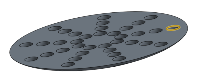
After weeks trying to figure out how to test hardware, I created the following part:

Turns out this simple part explains many taxing solid modeling issues that should be managed and are usually ignored by most engineers. Understanding why this simple part is taxing to a solid modeler is beneficial to anyone using/building with this technology. The test, which took about 45 seconds to run, timed how long it took to build the part; timed zooming in/out, rotate, hidden line remove; and then timed saving to disk. It was so simple yet did quantify differences between workstations and we began compiling a list determining which work station worked best.
The first aspect for creating a taxing part was to create a part that required a lot of CPU for regeneration. The curved bottom intersecting with cylinders creates a real problem for solid modelers. To compute these intersections represents a surface to surface intersect algorithm, it's a guessing algorithm. The intersection between these two surfaces is a guess at best and is the reason solid modelers have a tolerance. How accurately do you want this done? SW abstracted this tolerance accuracy out of the minds of engineers, so most don't care, but it's still there. Each hole intersecting the dome must be pain stakingly computed. If the bottom dome was replaced with a flat face, this eliminates the need to guess and an empirical solution is processed in a snap. Analytical surface intersections (cylinders against planes) compute fast, no guessing involved. Two parametric (spline based) surfaces intersecting, watch out.
Analytic surface to parametric surface intersect (hard):

Analytic surface to analytic surface intersect (easy):
Shaded screen images are the result of shaded polygons and controlling polygon count helps performance. A thousand cubes renders much faster than a thousand spheres. The dome bottom of our simple part was a minor tax on the video card but it still produced comparable results. You have to pay attention to the rendered shapes.
Rendering (easy):

Rendering (hard):

A simple act of downloading a bolt from McMaster Carr and using it in 2000 places can slow a system way down. One bolt with a helix sweep can kill a project. You're better off extruding a cylinder over the thread to remove the sweep and reducing the polygon count.
Occlusion, contribution & backface culling are processes to remove insignificant polygons from the display list. Removing polygons that face backwards relative to the display or removing polygons that resolve to a pixel takes longer than just rendering them. There is no display list optimization (at least in 1998). If you have a helix sweep but can't see it, it doesn't matter your zoom or the fact that it's hidden by other geometry, it still renders. The best way to control the display list is to control the geometry. If it's in the model, it renders and slows down. If the geometry doesn't matter, remove it.
I get it, you're an artist, create a simplified representation for working/designing and only use the complex stuff when you're printing something out, high end rendering or screen capturing an image.
-So many just keep piling it on without any regards to performance.
-You have to understand what's easy or difficult for solid modelers to handle.
-At the end of a project isn't a good time to learn.
-All solid modelers suffer from technology barriers and understanding how they work can be beneficial.
Sorry about the bitch, but I keep seeing the same problem over and over again.
In 1998 a good friend, Steve Wolfe (CAD/CAM Report Author) asked if I would run some hardware test on various work stations he had received from suppliers. How do you test hardware? There were floating point tests and polygon processing tests but nothing that applied to solid modelers.
After weeks trying to figure out how to test hardware, I created the following part:
Turns out this simple part explains many taxing solid modeling issues that should be managed and are usually ignored by most engineers. Understanding why this simple part is taxing to a solid modeler is beneficial to anyone using/building with this technology. The test, which took about 45 seconds to run, timed how long it took to build the part; timed zooming in/out, rotate, hidden line remove; and then timed saving to disk. It was so simple yet did quantify differences between workstations and we began compiling a list determining which work station worked best.
The first aspect for creating a taxing part was to create a part that required a lot of CPU for regeneration. The curved bottom intersecting with cylinders creates a real problem for solid modelers. To compute these intersections represents a surface to surface intersect algorithm, it's a guessing algorithm. The intersection between these two surfaces is a guess at best and is the reason solid modelers have a tolerance. How accurately do you want this done? SW abstracted this tolerance accuracy out of the minds of engineers, so most don't care, but it's still there. Each hole intersecting the dome must be pain stakingly computed. If the bottom dome was replaced with a flat face, this eliminates the need to guess and an empirical solution is processed in a snap. Analytical surface intersections (cylinders against planes) compute fast, no guessing involved. Two parametric (spline based) surfaces intersecting, watch out.
Analytic surface to parametric surface intersect (hard):
Analytic surface to analytic surface intersect (easy):
Shaded screen images are the result of shaded polygons and controlling polygon count helps performance. A thousand cubes renders much faster than a thousand spheres. The dome bottom of our simple part was a minor tax on the video card but it still produced comparable results. You have to pay attention to the rendered shapes.
Rendering (easy):
Rendering (hard):
A simple act of downloading a bolt from McMaster Carr and using it in 2000 places can slow a system way down. One bolt with a helix sweep can kill a project. You're better off extruding a cylinder over the thread to remove the sweep and reducing the polygon count.
Occlusion, contribution & backface culling are processes to remove insignificant polygons from the display list. Removing polygons that face backwards relative to the display or removing polygons that resolve to a pixel takes longer than just rendering them. There is no display list optimization (at least in 1998). If you have a helix sweep but can't see it, it doesn't matter your zoom or the fact that it's hidden by other geometry, it still renders. The best way to control the display list is to control the geometry. If it's in the model, it renders and slows down. If the geometry doesn't matter, remove it.
I get it, you're an artist, create a simplified representation for working/designing and only use the complex stuff when you're printing something out, high end rendering or screen capturing an image.
-So many just keep piling it on without any regards to performance.
-You have to understand what's easy or difficult for solid modelers to handle.
-At the end of a project isn't a good time to learn.
-All solid modelers suffer from technology barriers and understanding how they work can be beneficial.
Sorry about the bitch, but I keep seeing the same problem over and over again.
-1
Comments
interesting points and I'm sure everyone here has reached the brick wall in CAD many times, but as ine of those artist engineers I have to add that sometimes we need to model the complexity in to get a result we can use. This kind of links to my comments on the direct modelling thread, in that lego block modelling is easy in any application these days. Its the complex stuff that sorts the men from the boys. Geometry sure as hell is not done yet.
that project I mentioned? To complete it we had to use 5 different apps.
Illustrator and VectorWorks to do the 2D pattern.
Rhino to wrap the pattern into a 3D form (we tried in SolidWorks as a sheet metal part...no go...Rhino took 2 mins)
SolidWorks to do the engineering internals and prep for 3D printing
Modo for visuals.
now had Onshape been able to extrude that pattern, then wrap it, then handle the prep work, I would be seriously impressed. Maybe I'll upload the file and see how Onshape handles edits...see if that multi license Parasolid thing actually works or not.
I get it though, NDA's. Can't share.
Is it part of the queens jewels?
Twitter: @onshapetricks & @babart1977
Linked[in]