Welcome to the Onshape forum! Ask questions and join in the discussions about everything Onshape.
First time visiting? Here are some places to start:- Looking for a certain topic? Check out the categories filter or use Search (upper right).
- Need support? Ask a question to our Community Support category.
- Please submit support tickets for bugs but you can request improvements in the Product Feedback category.
- Be respectful, on topic and if you see a problem, Flag it.
If you would like to contact our Community Manager personally, feel free to send a private message or an email.
Consolidating pieces of your workflow into robust and simple features
 kevin_o_toole_1
Onshape Employees, Developers, HDM Posts: 565
kevin_o_toole_1
Onshape Employees, Developers, HDM Posts: 565
FeatureScript features are great at making small, functional pieces of models. Because they live inside your feature tree, you can use many of them, reorder them, and pass in your robustly-defined geometry: they'll update to downstream changes just like everything else.
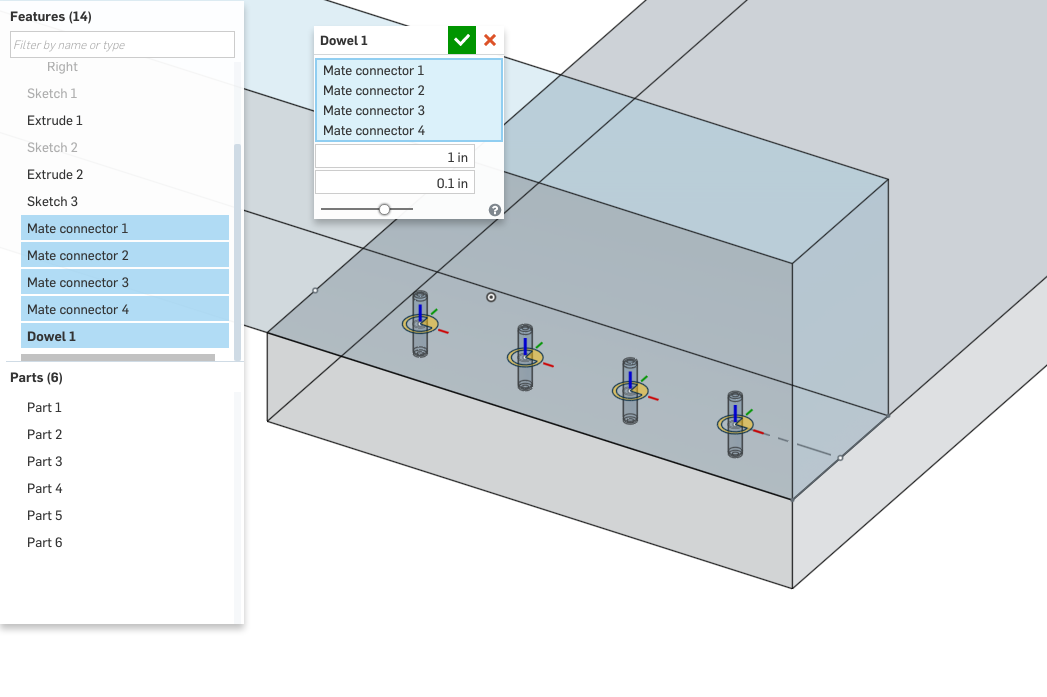
3DCAD brought up the idea of a dowel feature in a different thread, and I thought it warranted a top-level post. I made a quick prototype of a dowel feature. The feature takes in mate connectors, and for each connector, it will:
One interesting thing to think about here is making a wrapper around this feature: a feature which simply calls the dowel feature with a fixed size for the dowel's diameter and length. You could fill your part studios with these standard dowels. Then, if you decide to switch dowel sizes, simply update the wrapper feature, and all your dowel sizes will change.
Naturally, the above is also possible with variables, but you could imagine, say, changing the dowel's fillet to a chamfer, and seeing that update propagate. As you learn to make features take on larger roles in your models, this feature architecture can be quite impactful.
---
Here's the full text of the dowel feature (it's pretty short, but I'm sure more mechanically-minded people could think of ways to improve it).
3DCAD brought up the idea of a dowel feature in a different thread, and I thought it warranted a top-level post. I made a quick prototype of a dowel feature. The feature takes in mate connectors, and for each connector, it will:
- Cut holes in the surrounding parts for the dowels to fit in, and
- Creates a new dowel part, which is just a cylinder with both edges filleted.

One interesting thing to think about here is making a wrapper around this feature: a feature which simply calls the dowel feature with a fixed size for the dowel's diameter and length. You could fill your part studios with these standard dowels. Then, if you decide to switch dowel sizes, simply update the wrapper feature, and all your dowel sizes will change.
Naturally, the above is also possible with variables, but you could imagine, say, changing the dowel's fillet to a chamfer, and seeing that update propagate. As you learn to make features take on larger roles in your models, this feature architecture can be quite impactful.
---
Here's the full text of the dowel feature (it's pretty short, but I'm sure more mechanically-minded people could think of ways to improve it).
FeatureScript 275;
import(path : "onshape/std/geometry.fs", version : "275.0");

export const SMALL_LENGTH_BOUNDS =
{
    "min"        : -TOLERANCE.zeroLength * meter,
    "max"        : 500 * meter,
    (meter)      : [0.0, 0.005, 500],
    (centimeter) : 0.2,
    (millimeter) : 2.0,
    (inch)       : 0.1,
    (foot)       : 0.01,
    (yard)       : 0.005
} as LengthBoundSpec;

annotation { "Feature Type Name" : "Dowel" }
export const dowel = defineFeature(function(context is Context, id is Id, definition is map)
    precondition
    {
        annotation { "Name" : "Dowel locations", "Filter" : BodyType.MATE_CONNECTOR }
        definition.connectors is Query;
        annotation { "Name" : "Length" }
        isLength(definition.length, LENGTH_BOUNDS);
        annotation { "Name" : "Diameter" }
        isLength(definition.diameter, SMALL_LENGTH_BOUNDS);
    }
    {
        var count = 0;
        for (var connector in evaluateQuery(context, definition.connectors))
        {
            const dowelId = id + "dowel" + count;
            // Draw a circle in the XY plane of the mate connector
            const sketchPlane = plane(evMateConnector(context, {
                   "mateConnector" : connector
            }));
            var circleSketch = newSketchOnPlane(context, dowelId + "sketch", {
                    "sketchPlane" : sketchPlane
            });
            skCircle(circleSketch, "circle", {
                   "center" : vector(0, 0) * inch,
                   "radius" : definition.diameter / 2
            });
            skSolve(circleSketch);

            // Substract a hole from the parts in "merge scope"
            extrude(context, dowelId + "extrudeCut", {
                  "entities" : qSketchRegion(dowelId + "sketch"),
                  "endBound" : BoundingType.SYMMETRIC,
                  "depth" : definition.length / 2,
                  "operationType" : NewBodyOperationType.REMOVE
            });

            // Extrude a dowel
            extrude(context, dowelId + "extrude", {
                  "entities" : qSketchRegion(dowelId + "sketch"),
                  "endBound" : BoundingType.SYMMETRIC,
                  "depth" : definition.length / 2
            });

            // Fillet its edges
            opFillet(context, dowelId + ("fillet" ~ count), {
                  "entities" : qCreatedBy(dowelId + "extrude", EntityType.EDGE),
                  "radius" : definition.diameter / 4
            });

            // Increment the id count
            count += 1;
        }
    }, { });
1
Comments
thanks for this amazing yet simple example.
Few questions:
Can you create mate connectors with FS? I would expand your great example to include amount of dowels and step (with direction) so that it would work with only one manually inserted mate connector.
I suppose it could use also pattern rather than multiple mate connectors - though all this will be a problem in BOM
I didn't find documentation on how to create second direction for extrude since our 8x35mm dowel mounts 25+10 to holes that are 26+12 mm deep.
Can you please push me to right direction, thanks
opMateConnector, in geomOperations. You need acoordSystemto tell it where to go, and a query for the body to attach it to (likely aqCreatedBy).The answer to creating identical parts will be a bit more long-winded
There are a few strategies in general for handling duplicate parts. The easy path is to do what I did: make several copies in the part studio, and use everything in the part studio once in the assembly. This is non-ideal, because
- You'll need to rename every instance of the dowel, and keep those names the same (yuck)
- For more complex parts, you don't want to be storing multiple copies in the part studio. If the part is complex, you'll see performance hits in every direction: memory, graphics, regeneration times...
A better solution would be to make only one dowel per feature, no matter how many holes the feature makes. Then, the multiple copies can be added to the assembly either manually or via the replicate tool. In my original code, you can make this modification by wrapping the dowel creation portion in an "if" statement (e.g.if (count == 0)).This is still not quite ideal because you can still make multiple features with one dowel and end up with multiple identical parts. To fix this, we can store a variable in the context that says "Hey, I already have a part with identical parameters" to let FeatureScript know not to make another part. You can store and read this global state on a map variable with
assignVariableandmakeLookupFunctionin the std module variables.Here's a small sample of code that can do this. I tried it out, and it seems to behave well, choosing not to make matching dowels if and only if an identical dowel was made in the context before:
// Check if we've created a dowel identical to this (i.e. matching length and width) in this context before const currentDowelSpec = { "length" : definition.length, "diameter" : definition.diameter }; var existingDowelSpecs = makeLookupFunction(context, id)("existingDowelSpecs"); if (existingDowelSpecs == undefined) { // existingDowelSpecs is a map whose keys are the specs, stored as a the global variable #existingDowelSpecs existingDowelSpecs = {}; } var matchingSpec = existingDowelSpecs[currentDowelSpec]; if (matchingSpec == undefined) // No matching dowel, so create one { // Set the current spec to true, a flag that says "I've already made a dowel like this" existingDowelSpecs[currentDowelSpec] = true; // Update the context with this change assignVariable(context, dowelId + "specs", { "name" : "existingDowelSpecs", "value" : existingDowelSpecs }); /* Code for making a new dowel part */ }While waiting for perfect BOM, I would like to build a feature that handles:
- Create (add) a cylinder in place of predefined mateconnector
- Pattern cylinder x times with y spacing (direction?)
- Extrude / remove holes to other part to make room for new cylinder, depth 12mm
I have also another similar idea for building a fs for minifix (image from google):
But as @julian_leland mentioned in another discussion, it is not that easy to get started with current documentation.
This works, but if I change it to ADD it will combine both panels and dowels into same - what I need is to combine dowels to one panel 'head' and create holes to another panels 'surface'. I also tried to add boolean after creating new part but couldn't run without errors.
Any help appreciated.
Sounds correct: the behavior you're seeing is the same behavior you'd get if you were to extrude the dowel between the parts with the "add" option. In Onshape, we solve this problem with the "merge scope": a way to select precisely which parts get merged with the newly created body or bodies.
In the underlying FeatureScript, this parameter is call "booleanScope". (that part wasn't well-documented well now, but it's defined in booleanStepScopePredicate, in boolean.fs).
To allow merge scope selection, you can add it to your precondition:
annotation { "Name" : "Merge with part" }
definition.shouldMerge is boolean;
if (definition.shouldMerge == true)
{
    annotation { "Name" : "Part to extend", "Filter" : EntityType.BODY && BodyType.SOLID }
    definition.mergeScope is Query;
}
And then modify both extrudes. For the cut, you'll need to exclude the merge scope:// Subtract a hole from the parts extrude(context, dowelId + "extrudeCut", { "entities" : qSketchRegion(dowelId + "sketch"), "endBound" : BoundingType.SYMMETRIC, "depth" : definition.length / 2, "operationType" : NewBodyOperationType.REMOVE, "booleanScope" : definition.shouldMerge ? qSubtraction(qEverything(EntityType.BODY), definition.mergeScope) : undefined });And for the creation, you'll need to include it:// Extrude a dowel extrude(context, dowelId + "extrude", { "entities" : qSketchRegion(dowelId + "sketch"), "endBound" : BoundingType.SYMMETRIC, "depth" : definition.length / 2, "operationType" : definition.shouldMerge ? NewBodyOperationType.ADD : NewBodyOperationType.NEW, "booleanScope" : definition.mergeScope });One cool thing to note is that the fillet is already robust enough to not need updating. We specified a fillet ofqCreatedBy(dowelId + "extrude", EntityType.EDGE), a query for all edges created by the dowel extrude. When making a full dowel, that fillets its two edges. When making a half-dowel, that fillets one edge, as expected.The minifix also looks like a good project!
Since complex modeling can eventually get cumbersome in FS, I'd recommend you make just the holes in FeatureScript, and define the part geometry in another part studio.
If you want, you can also build those parts as part of the feature (by importing your part studio into your feature studio). However, in this case, I'm guessing you might as well just add the parts in the assembly.
Eventually, we'll have a good interface for cross-document imports. At that point, you could put both the parts and the mounting feature inside a single document. Then, you (and others!) can import that document into any place you need it in Onshape.
Thanks a lot, I will try these and probably come back with another question
Next I would need to add 'pattern' for mate connector in the beginning so that feature needs only one manually inserted mate connector and fs will create the rest. Is this the best way (multiply mc and add body to each) or is there some better way to pattern dowels along part?
I'm thinking to just create holes for minifix, since that is something I would like to use as instance when we get cross doc insertion in assemblies.
I hope we will see something similar as FeatureScript in assembly mode too to automate similar processes (like exploding dowel / minifix connections into assembly instructions).
You've rightly pointed out that this mergeScope is difficult to debug. The direct problem is that my code doesn't correctly set the "defaultScope" variable, a boolean which controls whether everything is merged together.
However, I'd actually recommend you fix this by making something easier to debug: rather than call extrude with a built-in union (as I suggested), I would try separating the extrude from the boolean. That is, call `extrude` with `NewBodyOperationType.NEW` always, and follow it up with an opBoolean with `BooleanOperationType.UNION`.
This way, when you get unexpected results, you can comment out all but the parts you're debugging, and use the debug function on the "tools" query you're passing into opBoolean. This query will probably be something like:
qUnion([
       definition.mergeScope,
       qCreatedBy(dowelId + "extrude", EntityType.BODY)
])
I'd also remove the hole as the same two steps: first extrude, then `opBoolean` with `BooleanOperationType.SUBTRACTION`. The targets for this opBoolean are "every solid body except the mergeScope", meaning the query will be something like:The debug function will highlight the result of a query (or other things!) in red when the feature dialog is open. We're interested in hearing your experience with it, and how useful it is for diagnosing errors.
ps. I agree with difficult debugging, I tried to separate different phases but as you pointed out it is not possible since things happened simultaneously and affected to each other.
I will try also debug feature.
I ask this as many of my ideas for features will require patterning. ie turret punch tooling features in sheetmetal parts.
Twitter: @onshapetricks & @babart1977
Patterning new bodies (i.e. anything unmerged) should always be possible in Onshape, like so:
Patterning already-merged entities is possible through a face pattern, like so:
Patterning a feature is not yet possible in Onshape. You can't pattern a "Dowel" feature just like you can't yet pattern an "Extrude" feature. However, feature pattern is definitely on Onshape's agenda for the future, and when it gets added, it will work for FeatureScript features you write just as well as it will for a native Onshape feature like extrude.
It is very helpful to create feature in modeling space and show script for part studio.
Can you please provide an example on how to a) include parts in boolean b) include any 'manually' modeled part in any feature (no by select but using code)
Thanks!
Twitter: @onshapetricks & @babart1977
I imagine this could be done similar to the dowel example by positioning the feature with a mate connector. Ideally different cavity sizes and types could be included into the dialogue. I would not bother including the cartridge in the Part Studio this could be added to an assy with the mate connector.
If modelling these I would construct a sketch and do a revolve remove. However in feature script would it be better to construct using a series of subtracted cylinders?
Can the script from a sketch in part studio be copied into a feature script? then revolved?
Twitter: @onshapetricks & @babart1977
In FS, you can either make a sketch and do a revolve-subtract (for the sketch you probably wouldn't set up constraints, just calculate the points directly and pass them into skLineSegment) or you can remove many cylinders (likely a little less efficient to regen, but that should not matter much). Another possibility is to manually construct in a part studio the body to be removed and then import it, transform it to the mate connector position and boolean-subtract it. We'll post an example doing something like this. You can also copy-paste from a part studio the code for a sketch on a default plane -- that should work inside a custom feature (just make sure you also copy the initial guess currently at the end of the part studio).