Welcome to the Onshape forum! Ask questions and join in the discussions about everything Onshape.
First time visiting? Here are some places to start:- Looking for a certain topic? Check out the categories filter or use Search (upper right).
- Need support? Ask a question to our Community Support category.
- Please submit support tickets for bugs but you can request improvements in the Product Feedback category.
- Be respectful, on topic and if you see a problem, Flag it.
If you would like to contact our Community Manager personally, feel free to send a private message or an email.
Feature Script for a break off tab for bending.
 bryan_lagrange
Member, User Group Leader Posts: 969 ✭✭✭✭✭
I come across this obstacle many times.
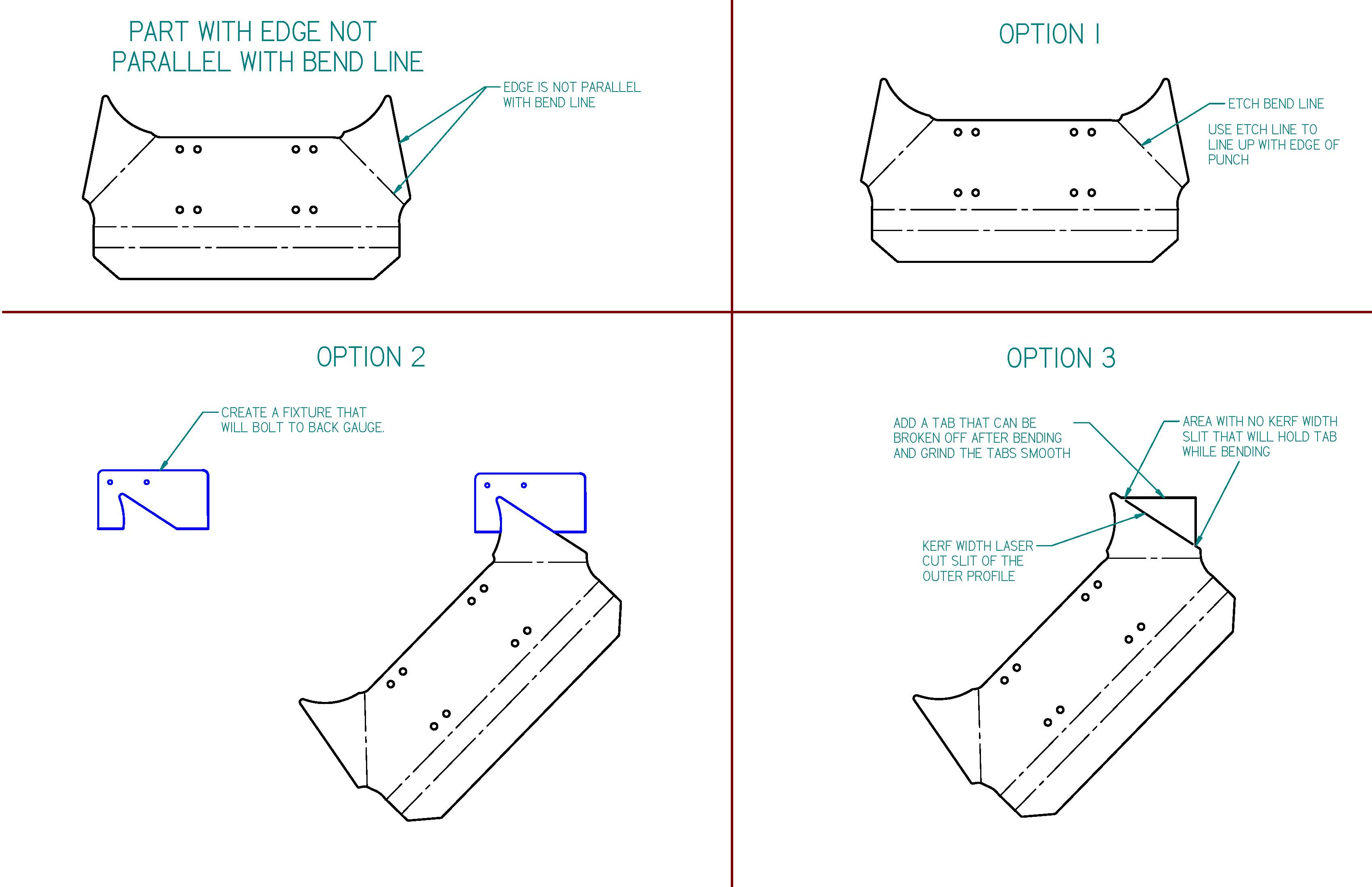
I have a part that I need to bend but the bend line is not
parallel with edge to gauge from. Since we do not have a press brake with back
gauges on different axis I have to do one of the following.
1) Etch the bend line then manually orient it between punch and die (not good for big run of parts)
2) Create a fixture that will attach to the back gauge and is
in the shape of the contour of the part or gets the edge parallel with the bend.
3) Create a break off tab by adding a tab to the end that
will create an edge that will be parallel with the bend line. After bending, the tab is broken off and the edges are ground smooth.
Do you guys think this would be a good feature script to
create option 3. If so anyone up for the challenge of creating this feature script? ![]()
Attached is a .pdf of what I described above along with
images.


Best Answer
-
 jon_sorrells
Onshape Employees Posts: 52
  Added some manipulators for the width of the tab: https://cad.onshape.com/documents/eea009fcf35a0cd683265767/v/107cf4854dc70cbeed63cc98/e/b692addf96e4fd22a1078b04
5
Answers
Twitter: @onshapetricks & @babart1977
Twitter: @BryanLAGdesign
https://cad.onshape.com/documents/eea009fcf35a0cd683265767/v/4e888b5e5ed8eb49ddedb1fd/e/bcd29e4ce588a4a8309e55cb
The two edges you select need to be on the same face. The hole/slit only works if the edge is straight.
Edit: updated link to V2 of the document, should be a little faster now.
Twitter: @BryanLAGdesign
Owen S
HWM-Water Ltd
New version that does that: https://cad.onshape.com/documents/eea009fcf35a0cd683265767/v/bb290273762822d3864db4cd/e/b692addf96e4fd22a1078b04
Here's the before and after of what it is lining up with
Twitter: @BryanLAGdesign
Twitter: @onshapetricks & @babart1977
https://cad.onshape.com/documents/eea009fcf35a0cd683265767/v/0b12bb7ba33af1d7159428b2/e/b692addf96e4fd22a1078b04
Twitter: @BryanLAGdesign
One of my coworkers suggested adding additional connections for the tab, so now there's an option for that.
Also, it can now handle more complex curves than it could before.
I wonder if it would be easier for the operator if the snap off parts were inboard a bit?
This way there is a definitive edge on either side to grind back too.
Cheers, Owen S.
HWM-Water Ltd
OwS
HWM-Water Ltd
Here is a curve ball for you @jon_sorrells . There are instances when I have a part with multiple bends and none of the bends are parallel with the outer edge. In this case I have to make more than one break off tab on the edge so that there is at least one edge parallel with each bend line.
@jon_sorrells can the feature script be adjusted to do this? (crossing fingers for a yes)
Here is a sample Onshape doc: https://cad.onshape.com/documents/971b4aa220787b5e7a9b3533/w/619f9a0b00182d01d30ccc32/e/44e8ab4cfd76821e05e2f175
Bryan
Twitter: @BryanLAGdesign
Take a look at this sample
Eduardo Magdalena C2i Change 2 improve ☑ ¿Por qué no organizamos una reunión online?
Partner de PTC - Onshape Averigua a quién conocemos en común
@emagdalenaC2C The modeling of the part design is not an issue. As shown in the example I can design it. The extra effort is needed when manufacturing this part. If you do not have a 6 axis press brake you need to create something to get an edge parallel with the bend line to make the bends. I normally create break off tabs to do this. The break off tabs are manually added to the flat pattern.The feature script shown here is an example of automating this function. The trick now is to get multiple bend tabs on the edge to be parallel to the bends.
Twitter: @BryanLAGdesign
Twitter: @onshapetricks & @babart1977
When I have to use the same edge of the part to place my bend tabs, for multiple bends, at different parallel orientations, I will have the tabs stick out at different height intervals with different widths. This is so I can note on the print which tab is for which bend and it also makes it easier for the operator to see and match the part to the print.
Twitter: @BryanLAGdesign
Do you have and example with the drawings noting the different tabs for bends?
Twitter: @onshapetricks & @babart1977
And would you expect this to take one instance of the Break off tab feature or two?
Nice work @jon_sorrells. I never though of using example l before with different profile edges on l tab. Something to try next time.
Could you have it where we can specify the width of the break off tab. I don't have to have them the full length of the edge for the break off tab.
Below is an example of how I would have made my manual changes in 2D.
@brucebartlett This is an example of how I create multiple bend tabs and label them to help the operator at the press brake. With a kerf width laser slit and a minimum tab to hold them you get a positive bend location using the back gauges of a press brake and minimum clean up after bending.
Small parts I use 1 break off tab. When I get larger longer parts I use 2 so that the operator can use both back gauge fingers and it gives the operator more stability when bending the part.
Twitter: @BryanLAGdesign
Twitter: @BryanLAGdesign
Twitter: @onshapetricks & @babart1977
https://cad.onshape.com/documents/eea009fcf35a0cd683265767/v/467c5a5872fdde831846abc9/e/b692addf96e4fd22a1078b04
If you update an old instance of the feature to use this version, you may need to toggle 'Opposite direction'.