Welcome to the Onshape forum! Ask questions and join in the discussions about everything Onshape.
First time visiting? Here are some places to start:- Looking for a certain topic? Check out the categories filter or use Search (upper right).
- Need support? Ask a question to our Community Support category.
- Please submit support tickets for bugs but you can request improvements in the Product Feedback category.
- Be respectful, on topic and if you see a problem, Flag it.
If you would like to contact our Community Manager personally, feel free to send a private message or an email.
Hollowing out a convoluted cylinder
 tj_thorniley
Member Posts: 65 ✭
tj_thorniley
Member Posts: 65 ✭
Was hollowing out this lens barrel, making progress. But for some reason, I can't seem to get the last bit (towards the right-hand side of the images below).
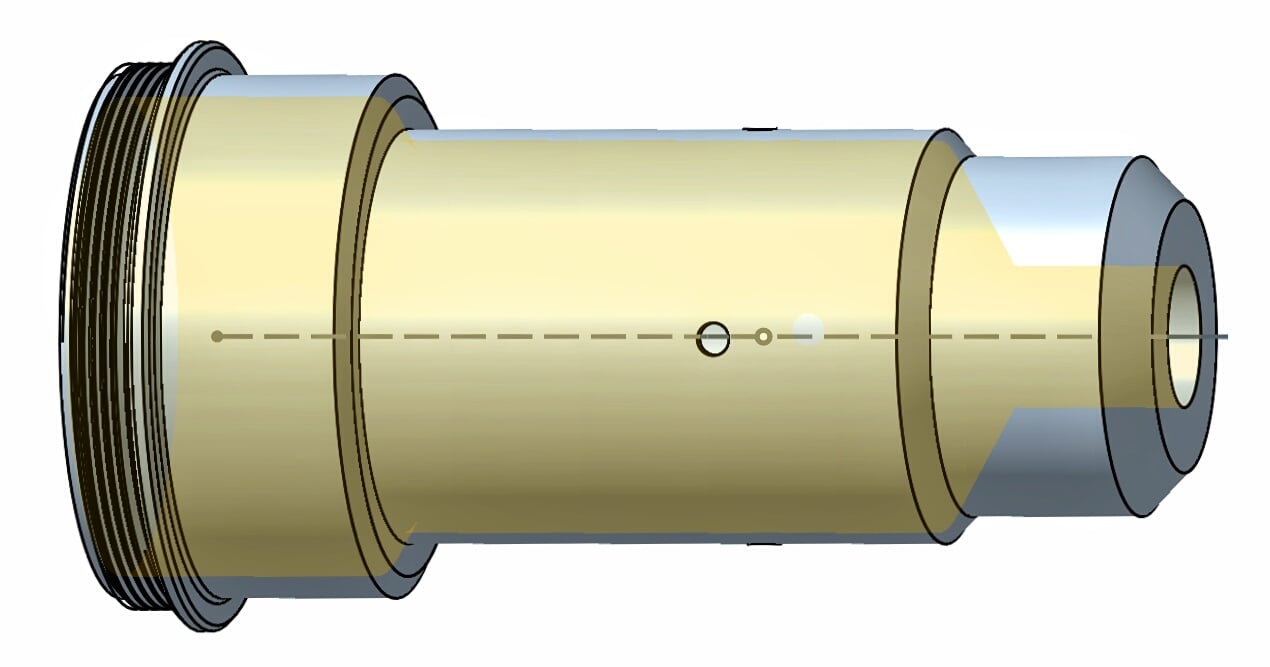
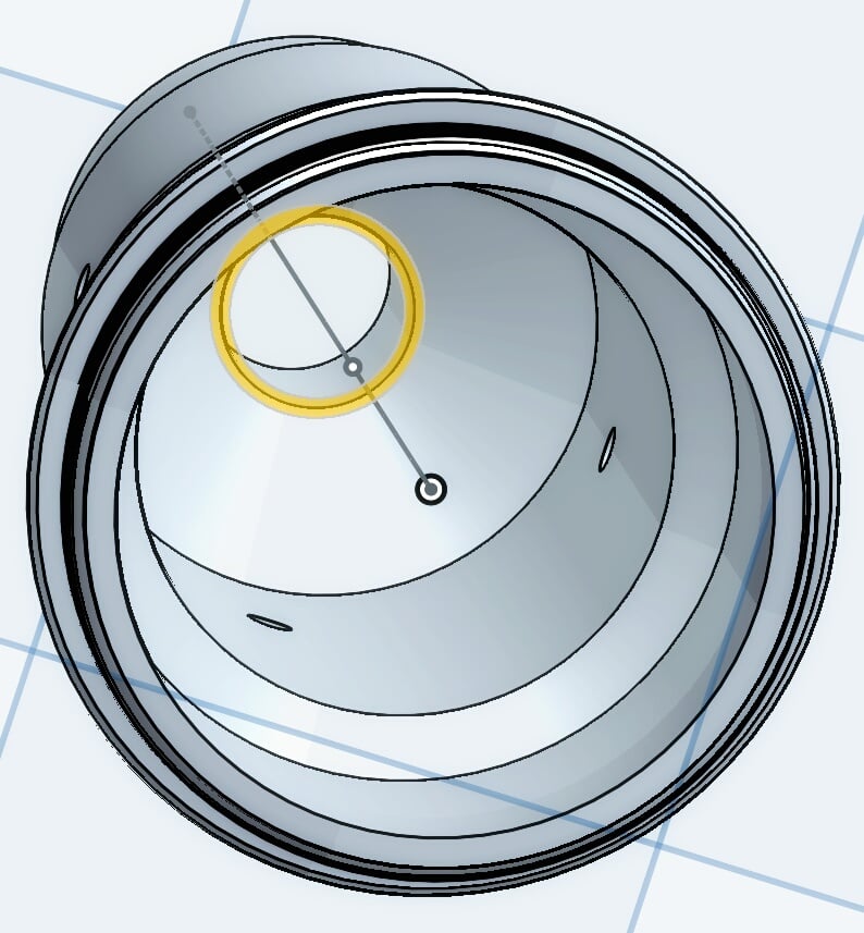
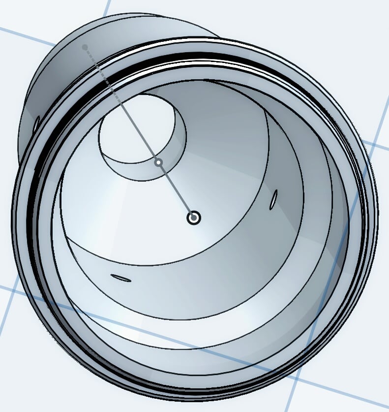
Any ideas? Here it is looking up the barrel.
https://cad.onshape.com/documents/b4b4261f4f1c26e011a77dbf/w/1b735737fb7eeb1a46eac899/e/aad0b319e095bf2cff3162c5
Any ideas? Here it is looking up the barrel.
https://cad.onshape.com/documents/b4b4261f4f1c26e011a77dbf/w/1b735737fb7eeb1a46eac899/e/aad0b319e095bf2cff3162c5
0
Answers
If so, just do a revolved cut. Also, I noticed that Hole9 and Hole11 are misaligned.
Also, are you talking about the small 1.5mm holes? I tried to get them perfectly in line, but I don't know how. I made the first one by making a 'point' and 'hole', flipped the model, expecting a new 'point' would snap in line with the one on the opposite side. But it didn't seem to recognise it.
Note that some of the chamfers are drawn - "functional" chamfers should be drawn, "cosmetic" chamfers should use the chamfer tool (as a rule). To get your hole around the circumference, draw a circle on the top plane and extrude/remove in both directions, then use the circular pattern tool to get the others.
Not trying to be a pain; I appreciate your advice. But for me, it's not so much about this one particular instance. It's more about understanding how to use the tools and becoming familiar with all associated the bits & pieces.
@tj_thorniley, what you were doing wrong was using the Hole feature. Hole features are generally used when making holes of preset shape/size for fasteners, e.g. specific fastener clearance sizes, counterbores, countersinks, etc. Asking why the Hole tool didn't work is akin to asking why you shouldn't use needle & thread instead of stapling sheets papers. I guess needle & thread could be made to work, but why would you bother figuring out how?
In your case, you wanted a very specific shape that more or less matches the outer contours of your lens barrel. That's what the Revolve feature is for, or possibly Shell. I suggest you learn to use those features and leave the Hole shenanigans behind - at least for this particular usage.
The reason your "Hole" tool is chopping off the end of your Part is because its subtracting a tool that looks like this red thing (but is going the other way from the selected sketch point):
I got this graphic by clicking the arrows next to "through", which switches the direction that the hole is being drilled.
In general, I wouldn't advise using the hole tool do hollow out a part like this. With the hole tool, you don't have control over the shape of the cone at the end and there are a lot of unnecessary options that you won't end up using. The hole tool is great for making drilled/tapped holes, but what you are trying to do here requires a bit more precision.
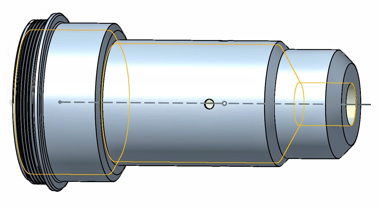
It's much simpler to just sketch a circle and extrude-subtract:
Or better yet, roll back to before the holes, sketch the cross section of the material you want removed, and do a revolve-remove:
Simple sketch using the "offset tool" ^
revolve remove ^
Document with these examples:
https://cad.onshape.com/documents/04d9d061ddaa16dfbde7bba0/w/3ed12fdc1d26d2637339e97d/e/490d09a182df864063ac2760
I think you'll get a lot farther by using sketches and simple, generic, robust tools like extrude, revolve, draft, and loft than trying to use a special purpose tool like Hole for something it wasn't meant for.
The hole tool is really meant for applications like this:
where you want to make a series of bolt-holes in one or more parts. The added value of the tool is that the selected options (ANSI vs ISO, sizing, countersink/counterbore, through) will show up on a drawing sheet for manufacturers.
Are there video tutorials for all the tools? I checked YouTube, but I think there's a lot that isn't covered on there.
You can learn all you need to know for free at learn.onshape.com or you should attend one of Cody's regular "Essentials" webinars where you can ask as many questions as you like, live.
P.S. Don't down vote me!
To everyone else: Not to go on about nothing, but I'm not the kind to just shut up and do what I'm told. It seems you're right; it's not the best way to do it. I've taken that advice on board. I appreciate it. And chances are, I'm going to end up doing it the way you've recommended. But when I'm determined to figure something out there's not much point trying to stop me. I experiment. It's how I learn. And sometimes, I simply want to know what I want to know. In this instance the reason why is kind of abstract and hard to explain. No disrespect intended. Just to be clear.
All things considered, it worked out reasonably well, although the final internal bevel is steeper than the required 45°. I'll probably end up going with Jake's 'offset' sketch → 'revolve' remove method.
---------------------------------------------------------------------------------
To make sure all the parts fit together perfectly, should I model them all in a single 'parts studio'? There are just a few non-moving internal parts. And a brown/gold outer shell with a fine thread that fits over the top. Yes, I'd like to model the thread.
Here's the shell:
Here's the original model where it was all one piece:
Here's the actual part that fits in the shell, so you can see where the thread goes (the middle one; I think the one to the right is vestigial):
Here's the first internal part (again):
Yes! You'd be best modeling all of these parts together in the same Part studio to make sure they fit together nicely. The Boolean tool is your friend here (as well as the boolean options at the top of our feature dialogs), because you could do something like creating the positive of the threads, and then doing a "Subtract" to get the negative.
https://www.onshape.com/cad-blog/tech-tip-booleans-in-onshape
Additionally, you might find the "Thread Creator" custom feature helpful. It can be found on this page: https://www.onshape.com/featurescript by hitting the "More" button at the bottom of the "Feature Spotlight". If you've never used a custom feature before (custom features are Onshape features written by the community), check out the "Start Using Custom Features" video on that page.
Was there anything else you were wondering about? I'm not sure if I'm missing another question in your post.
Best
You're welcome to use any of my parts as examples if you like. I think it could be useful for everyone.
You may find this page helpful:
https://www.onshape.com/videos
I'm not very good at making videos (my main role here at Onshape is as a programmer). We try to discourage making threads in general ( @owen_sparkshad a great post on the end of this chain about how adding threads made his model >100x more complicated for our system https://forum.onshape.com/discussion/comment/33855#Comment_33855), unless it's absolutely necessary from a modeling standpoint, so I'm not sure we'll make that kind of video tutorial any time soon.
I'm definitely happy to help though! Instead of a video I've made you a couple part studios:
https://cad.onshape.com/documents/6df3507dd25c816a1d437ad7/w/6a706b78f17354ea71494aa7/e/2ffd79d230b17d4c11d33e18
You can copy this document and double click on any of the features to see what the inputs and affect of that feature were. You can also drag the rollback bar to different points in the Feature List to see what state the document was in at that point in time.
This video has a good example of the best way to roll through the history of a document, starting at 3:58: https://www.onshape.com/videos/parametric-modeling-and-feature-based-modeling
I've taken two approaches in this document:
- In the "Using boolean" part studio, I created a bolt by rotation, created threads on it using the thread creator custom feature (see my last post for how to add this to your toolbar and use it), created a cylinder by rotation, and then did a "Boolean" with the "Subtract" option to carve the threads out of the cylinder
- In the "Using thread creator" part studio, I created a bolt by rotation, then created a cylinder by rotation and used a "Boolean" with the "Subtract" option to carve out the (unthreaded) bolt shape from the cylinder. I then used the thread creator on the outside face of the bolt and the inside face of the complimentary cylinder to make matching threads on both of the parts.
Please let me know if you have any questions about the document, or about looking through the feature list to deconstruct how a part was made.P.S. I did find these videos on creating threads:
https://www.onshape.com/videos/lets-build-a-thread-in-60-seconds
https://www.onshape.com/videos/lets-make-a-nut
but they are pretty old, and the thread creator is much easier to use than following these full sets of steps.
About to take another crack at hollowing out this part. Why can't I just use the 'shell' tool? I can get it to work perfectly on separate parts, including cylinders, etc. But for some reason it won't do the whole part. Something keeps tripping it up.
Sometimes the shell can create self-intersecting geometry on parts with small details (like threads). Since you want your shell to just respect the overall shape of the part anyway, I would design the simple shape of the part, then shell it, then add the details (all the threads and exterior lips etc.)
It's become pretty intricate with various 0.5mm extrudes, and tiny details.
This is my first model and its taken considerable time and effort to get it this far. So I'm trying my best to avoid scrapping it.
Measurements were taken with vernier calipers and a micrometer.