Welcome to the Onshape forum! Ask questions and join in the discussions about everything Onshape.
First time visiting? Here are some places to start:- Looking for a certain topic? Check out the categories filter or use Search (upper right).
- Need support? Ask a question to our Community Support category.
- Please submit support tickets for bugs but you can request improvements in the Product Feedback category.
- Be respectful, on topic and if you see a problem, Flag it.
If you would like to contact our Community Manager personally, feel free to send a private message or an email.
Improvements to Onshape - February 3rd, 2023



PART STUDIOS
BOUNDARY SURFACE
The Boundary Surface feature puts high quality surfacing into the hands of all Onshape users. The Boundary Surface approach uses sets of curves from each direction (the U and V direction) to form a 4-sided, closed surface, with options to specify boundary conditions such as tangency matching, normal to profile, etc...
CONTROL POINT GRID
A new option has been added to the Curve and Surface Analysis tool that displays a Control Point Grid that is useful for understanding the defining geometry of a spline surface.
MEASUREMENT OF ANGLES FOR CURVES AND FACES
When defining a surface, it is essential to know at what angle a curve or surface is intersecting another group of curves or surfaces. Note how the selection is possible between curves and surfaces that displays the angle numerically and graphically on-screen.
EXTRUDE DIRECTION
When performing an extrusion, the direction of an extrude can be defined using planes, lines and mate connectors. This improvement will facilitate the creation of geometry previously tricky to build with a single feature.
EXTRUDE OFFSET
To set the distance from the sketch plane when creating extrusions, an option is provided to select an offset to the starting direction of an extrusion as you create it—reducing the amount of reference geometry needed to create the same geometry.
CUSTOMIZE THE "S" KEY SHORTCUT TOOLBAR WITH CUSTOM FEATURES
Now all your favorite Custom Features can be added to your "S" key custom popup toolbar!
ASSEMBLIES
ASSEMBLY MATE FOLDERS
You can use Folders to store groups of mates, helping to organize mates for use when creating assemblies. Organized mates can be helpful when managing configurations, named positions, simulations, and more.
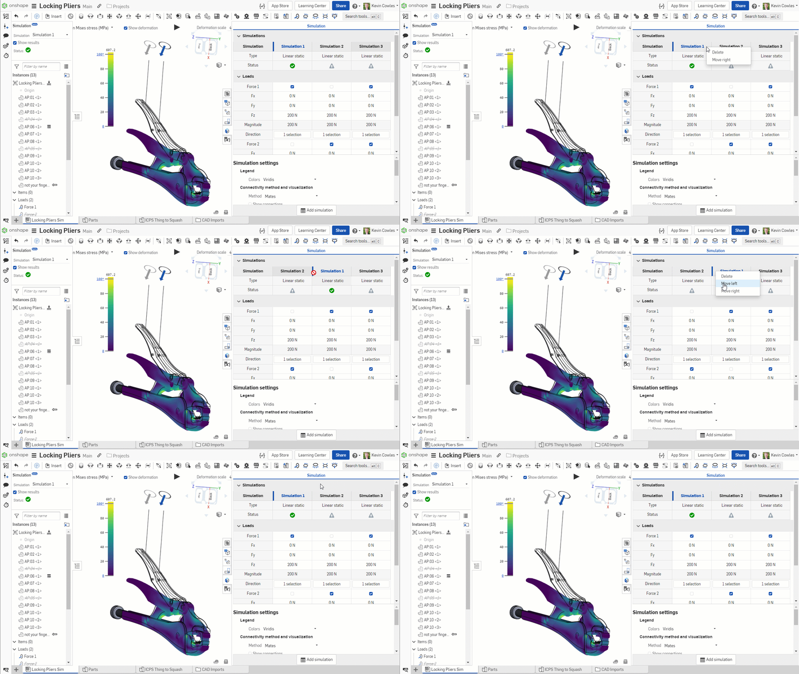
REORDER SIMULATION STUDIES
Use context menus on Simulation Studies to move right or left for better organization.
DRAWINGS
HATCH REGION
Dynamically created hatch regions are available in drawings with a pre-defined region or with new sketch geometry created on the fly.
HATCH STYLE PANEL
Use the Style Panel to edit one or more hatch patterns on the drawing.
INSPECTION REPORTING CALCULATES LIMITS
Inspection items in Onshape Drawings will auto-calculate the upper and lower bounds for all bubbled dimensions for your inspection reporting needs.PDM
CLONE PUBLICATION
A Publication can be cloned to allow for sharing of similar data with the extended design. Use cases include sharing a publication that includes different versions and revisions of data, sharing with a different group of users and more.
GENERAL TASK INSIDE A DOCUMENT
In addition to creating General Tasks from the Action Items screen (found under your profile picture menu or the Action Items tab across the top the screen in the Enterprise version), access Tasks inside a document by right-clicking on a tab or part/assembly. Tasks created in this manner automatically reference the selected entity.
EXPORT ITEMS TO A CSV
Items from company settings can now be downloaded as a CSV directly from the Company options. This allows for more flexible management of bulk items so that administrators can share this data with other business systems.

ENTERPRISE DASHBOARD UPDATE - MODELING TIME BY USER OVER TIME
FEATURESCRIPT
Several ease of use improvements have been introduced to FeatureScript.OPEN LINKED DOCUMENT FOR IMPORT REFERENCES
CTRL-click or CMD-click on a Mac now hyperlinks to and opens a new browser tab to the Import reference being called.PROFILER IMPROVEMENTS
AUTOCOMPLETE AWARE OF `->` PARAMETER
When using the arrow functions, autocomplete previously added in the first parameter, which gets in the way when chaining functions like queries together. This improvement handles the first parameter or not depending on whether it is in the expression chain.SHOW LOCAL VARIABLES FIRST
Local variables will now show up at top of autocomplete menu for convenience.ANDROID
EXTERNAL REFERENCES
For assemblies made with Linked Document references, export operations are allowed (as long as the export permission is allowed) from an Android device.

LEARNING CENTER
VIDEO UPDATES
A couple more videos have been updated in the Learning Center:Frames Fundamentals course
New video on adding Gussets to frame parts.Advanced Part Design course
New video on partial fillets.Please take a moment to try out these new features and improvements and leave your comments below. For a detailed list of all the changes in this update, please see the changelog.
Remember: The updates listed here are now live for all users when creating new Documents. Over the next few days, these features will also be available in Documents created before this update.
Comments
-
This one is full of bangers! Our team has been looking forward to the boundary surface, much thanks! Next step curvature control
 6
6 -
Definitely some good stuff in there!
I unfortunately do very little surfacing so I will miss out on some of these... I think the folders for mates are going to be my favourite from this round (been wishing for these for a while, especially since mates aren't automatically named after something useful and it gets tedious renaming them, at least we can now dump "related" mates in a folder to make it way easier to navigate...)!
The extrude tool refinements will be nice as there are some cases where the "other end direction" couldn't quite achieve the same as the offset. I was hoping for an "extrude thin" (a tab between solid and surface...) but I guess it's not that big a deal (yes, I know there's a custom feature somewhere that has that but I don't really want to use a "special" extrude...)5 -
Y'all! This is a killer update! Boundary, new Extrude options, surface control cage preview, the Featurescript quality of life stuff. So much to love.3
-
Extrude improvements for the win!!! Thank you Onshape team. Excellent work. This release is a big one!1
-
The new hatch regions are fantastic! Now, I can finally create a proper title block with a vector art logo using color fills!1
-
Extrude improvements are great, what I've always wanted but better. Great work. Thanks1
-
A great update! I bet a lot of product designer will be very happy!
Folders for mate connectors are very usefuly for big assemblies 0
0 -
Wow, lots of new stuff.1
-
When should one use boundary surface versus fill?2
-
I was very excited to see Boundary Surface and the new analysis tools... however doing a really basic test leads to disappointment.
Here are two sketched curves (on parallel planes) which are both degree 3 Béziers.
I create a very simple Boundary surface using these two curves and I get this:
It clearly rebuilds the two end curves to be 2 span, degree 3 B-splines (in U), and a nice degree 3 in V. In the middle, the U curvature is not G3. This seems bizarre. This is such a simple surface to get right.
Lofting with the same curves and constraints actually yields a much better result, even though it rebuilds the input curves with more density than Boundary:
I will definitely have to do a lot more investigation. Much like in Solidworks, there are times when its Boundary surface is better than Loft, and vice versa. The really great thing is that Onshape is giving us better analysis tools than many other CAD programs. I would often export critical surfaces out of Solidworks and look at them in Rhino, but with all the upgrades to Onshape's analysis tools, the only thing I'd still love to see is a built in environment map option.
[Edit]
On a little further investigation, I wonder how much of this could be an artifact of the U/V curvature analysis itself. Looking at zebras, or Gaussian, or mean, I can't detect any hint of the issues I see in the U-curvature. Hmmmmm.Simon Gatrall | Product Development, Engineering, Design, Onshape | Ex- IDEO, PCH, Unagi, Carbon | LinkedIn
3 -
Thank you for the link to the imported document in FeatureScript!!! Love it! I'll be using that frequently.1
-
Some more investigation of Boundary surface and the surface analysis tools...
Overall this will be very useful, but it's interesting what is not included right now:- Boundary doesn't have guide curves in the middle of a surface like Loft or Fill
- Boundary doesn't allow curvature constraints like Loft or Fill
If you use Boundary surface with just two U curves, and add tangency constraints, the V curves at the edges are very different than Loft. They aren't exactly what I would expect. Solidworks has some advanced tools to control how these edges are created, and I expect that something like that will show up in Onshape some day.
The great thing about seeing the control point grid is you can really see the results of building similar surfaces with Boundary, Loft and Fill. Depending on your needs one might be much better than the others. Sometimes Fill is producing a more well behaved, less dense control point layout than Boundary or Loft.
Here are the "same" transition surface built between two orthogonal extruded surfaces (from degree-3 Bézier sketches) with curvature continuous Bridging curves on the sides.
Boundary does a decent job, but there's no curvature option, it rebuilds the U curves, and I'm not sure I like the way the parameterization happens in the middle:
Loft has "Match curvature" but it has some horrible bunching of CVs on the edges. This kind of thing is fine for a single surface, but if you build a lot of things off of intersections or extensions of these edges, you may start to have weird wobbles or failures.
Fill has a curvature option, and it builds a surface without rebuilding either the U or the V inputs! In this particular case, I would choose Fill.
Simon Gatrall | Product Development, Engineering, Design, Onshape | Ex- IDEO, PCH, Unagi, Carbon | LinkedIn
4 -
Wow!1
-
@S1mon Thanks for diving in so soon, though we suspected (and hoped) you would be! Pease continue to give us feedback as we're eager to see how this new feature works for you all.
To address some very high level points you made - yes, the Boundary surface, Loft and Fill will behave differently, as their underlying intent (and mathematics!) is different. There is no one perfect feature, so having more options to cover all possible situations is the idea here. In some cases, Loft, Fill, or Boundary surf may give the result you desire, and in that case is the best choice.
That being said, we are striving to make each of these features (as you've seen over the past number of releases where improvements have been made) better. We of course don't talk about futures here, or forecast any release targets for improvements, but suffice to say we are not done with Boundary surface...
In fact if you have not already signed up for the Onshape Live event, then it might be a good idea - we do have a session on Sneak Peeks, and I invite everyone to come along and even participate in the Q&A with the people developing all this great stuff.
4 -
Frigen awesome. Thank you!1
-
Maybe a stupid question: what is (the difference between) an U- and V-profile in the Boundary surface feature?
3 -
I'm getting the new extrude features in newly created documents, but in my existing documents I'm still seeing the old features... Will they be updated automatically? Or do I need to do something?
0 -
See the footnote in the post.david_brophy said:I'm getting the new extrude features in newly created documents, but in my existing documents I'm still seeing the old features... Will they be updated automatically? Or do I need to do something?Senior Director, Technical Services, EMEA0 -
U and V are just the conventions for the names of the two parameters of a 4-sided surface described by some function f(u,v). Typically the values of U and V go from 0 to 1.Henk_de_Vlaam said:Maybe a stupid question: what is (the difference between) an U- and V-profile in the Boundary surface feature?
Think of a generic surface as being a thin sheet of rectangular rubber or wire mesh. They can be stretched or formed into 3D shapes, but they want to stay 4 sided. If you draw a grid on the flat sheet of material, one axis is called U, and the other is V. The two edges of U are “parallel” (in the theoretical flattened version) and the two edges of V are “parallel”.In the case of Boundary surface, it doesn’t matter for a given four sided boundary which pairs you choose for U or which you choose for V. You should get the same results.It’s also possible (like with Loft) to only pick two edges and let it make up the other direction.Simon Gatrall | Product Development, Engineering, Design, Onshape | Ex- IDEO, PCH, Unagi, Carbon | LinkedIn
3 -
That is indeed what I found with the boundary surface feature but did not know the background of it. Thank you for explaining.S1mon said:
...The two edges of U are “parallel” (in the theoretical flattened version) and the two edges of V are “parallel”...
2 -
Awesome update!!!
En este enlace podéis ver las Novedades de Onshape en español: https://youtu.be/pxCzkgAjcD8
Un saludo,
Eduardo Magdalena C2i Change 2 improve ☑ ¿Por qué no organizamos una reunión online?
Partner de PTC - Onshape Averigua a quién conocemos en común1 -
Great Update! Thank you.I love the new ability to add custom features to my fly toolbar (s), and the option to organize all the mates.Best regards,
Axel Kollmenter2 -
EXTRUDE OFFSET thank you!!
1 -
Is there a different between Extrude Offset and just flipping the Second end position direction? I have been using that since the beginning to do Extrude Offsets.2
-
Hi Mike, there are quite a few differences and there was a crazy amount of votes for this improvement - mainly, you don't have to do any mental maths to work out the second offset and you can apply draft from the offset plane. My main use case is when detailing bosses where the top of the boss is the critical dimension and then draft is applied from there. You can now sketch on the bottom face, offset and extrude/draft backwards up to next.mike_hölscher said:Is there a different between Extrude Offset and just flipping the Second end position direction? I have been using that since the beginning to do Extrude Offsets.Senior Director, Technical Services, EMEA4 -
Great work. I especially like Boundary surface. Extrude offset you could live without. But it will still be much more convenient than the current approach of defining a second extrude direction and substract that. Keep up the good work!1
-
I can myself making good use of the extrude offset and toolbar. Mate folders is definitely going to be the best quality of life improvement for me right now. Solid update!1
-
Join Richard Doyle, the User Group Guy and Mike LaFleche, the Professor, as we react to the latest updates to Onshape. This one is big! Lots of goodies in Part Studios, Assemblies, Drawings, PDM, FeatureScript and Mobile.
LinkedIn: https://www.linkedin.com/feed/update/urn:li:ugcPost:7028036523853807616
YouTube: https://www.youtube.com/watch?v=AKqwdWIlihg
Twitch:
Twitter: https://twitter.com/Onshape
Twitter: https://twitter.com/mlaflecheCAD
Regards,Mike LaFleche @mlaflecheCAD1 -
Thank you Onshape team!
RENDERCAD
rendercad.ai - Photorealistic product rendering.
▚▞▚▞▚▞▚▞▚
________________________________________________________________________4