Welcome to the Onshape forum! Ask questions and join in the discussions about everything Onshape.

First time visiting? Here are some places to start:
  1. Looking for a certain topic? Check out the categories filter or use Search (upper right).
  2. Need support? Ask a question to our Community Support category.
  3. Please submit support tickets for bugs but you can request improvements in the Product Feedback category.
  4. Be respectful, on topic and if you see a problem, Flag it.

If you would like to contact our Community Manager personally, feel free to send a private message or an email.

building a complex sheet metal part in context....

don_bdon_b Member Posts: 106 ✭✭
I wonder as to suggestions to obtain a flat pattern from a complex sheet metal part that has been built in context with added extrusion of more metal etc.... to a finished sheet metal part because addition extrusion (only subtraction) not allowed to the flat pattern.or unfinished sheet metal part.   
«1

Answers

  • NeilCookeNeilCooke Moderator, Onshape Employees Posts: 5,308
    Have you tried the Tab feature?
    Senior Director, Technical Services, EMEAI
  • don_bdon_b Member Posts: 106 ✭✭
    I have used the tab feature and it is very useful however the there is complex arraignment of parts in compound angle geometry.....Currently trying to just isolate the part in a separate document to play with it....however seems I am missing something as to the export function does not allow a part to be exported to another document in onshape unless I do it in step or parasolid  which seems ignorance on my part.
  • don_bdon_b Member Posts: 106 ✭✭
    I might try the tab feature at zero angle and extrude remove which is allowed 
  • eric_pestyeric_pesty Member Posts: 1,461 PRO
    It would help if you could share a document or at least show an image of what you are trying to do...
  • don_bdon_b Member Posts: 106 ✭✭
    https://cad.onshape.com/documents/2862cbdeaf8a076d3fba355d/w/a0f7522fb7e33463c5efe1e9/e/bfb6c14a11f44f5c13939efb

    the top half of part 106 is done...many additions, extrude remove etc...I think I could suggest many features but I am not sure if its just my ignorance rather than the software
  • shawn_crockershawn_crocker Member, OS Professional Posts: 798 PRO
    @don_b
    Oh wow!  There is a lot going on in there!  If I were you, I would use what you have done in this part studio as a learning experience for the reason you might want to take different approach completely.  I would start a completely new part studio and leave this one for referencing.  For something complex like this, I think you are trying to create usable parts too early on in the design.  I would try to create, with just a few features, the basic overall exterior shape of your design.  Then you can start digging in by drawing sketches, and splitting faces or splitting off pieces of the master model.  Adding and removing material easily with all the standard performant features.  I would try to do the majority of the geometric modeling while the model is still just a solid or surface body.  After that, it is easy to start creating really complex sheet metal parts by directly using the complex geometry you created on the master model.  Also because your model is rather large and there seems to be areas of the model that will probably end up becoming a subassembly or something, you can derive the master model into a new part studio so that you can focus on create parts for different sections of the design without it feeling so busy with everything crammed into on feature tree..
  • don_bdon_b Member Posts: 106 ✭✭
    Thank you....certainly is a lot going on and it is a learning experience.....I have always ( since 1975) designed "top down" (in context) as far as I am concerned it is the only way to design....that being said this design is pretty much finished in concept and is more complex that my last failed design because of the compound angles of the brace tubes and the gussets and z stiffeners being compound angles...I like the flat pattern routine as I have always calculated them 2D and with the compound angles that becomes much more difficult and prone to mistakes.  If you want to see the project and where I am currently go to the last page of my "build log"  and you can see actual parts...just for reference my rear spar fitting was off 1/2 " from theoretical in one direction because of mistakes in the 2D drawings, which is why I am playing here. Given the steps in the tubes and offsets of thickness of the sheet metal gussets I am not sure I understand how I would do it as you describe but thank you very much for your comments and interest.    As I go along I certainly am coming up with basic geometric edit and transformation  features I need to learn or perhaps need addition to the sheet metal module and software generally.  Basically for the last 25 years I have used Autocad14 as my main ride as a consulting self employed  design engineer. (retired).
    https://www.homebuiltairplanes.com/forums/threads/aluminum-dragon.24732/post-708445
  • glen_dewsburyglen_dewsbury Member Posts: 559 ✭✭✭
    Hey @don_b
    I gotta go with Shawn plus some comments of my own.
    Leaving behind failed features is likely to cause problems further along. Some parts will still display but not be fully functional. I tried to add something to a sheet metal part as a how to example but could not select a sketch face.
    Building a part then transforming into position is the hard way. Find a way to build in place. It's a lot less work and easier to follow later.
    Also noted sheet metal parts booleaned together. It is way better to brush up on sheet metal techniques to add flanges and extensions. If all is working well you can add in sheet metal view. The bits added by Boolean weren't reflected in sheet metal view. There are some things to get used to but the end result is way more robust. Lots of good resources on the forum. I just got help myself from the last webinar from a couple of people that work in sheet metal shops.
    Your spline sketches imported through DXF as multy lines are a bad way to make sweeps. Use 2 or 3 points provided and build new splines to match.
    You don't need to multy pick profiles for the sweep. The area between circles works fine.
    Here are a couple samples. Hope this helps. Cheers Glen
    https://cad.onshape.com/documents/72a31f2614e3be5f6fc86179/w/91f5be37b10d2dfad322a257/e/dc482ffd24bf8d5d36ca44ba
  • don_bdon_b Member Posts: 106 ✭✭
    Thank you..... the hints provided have lead me in poper directions....and both the Tab addition and spline adjustments I have learned after the  improper feature construction.....I was not able here to make a continuous polyline or spline suitable for use in Loft because of the need for exact equal segments....My Loft generations are a proper result....the original polylines are from my original Autocad digitized rib profiles and in Autocad ruled surfaces were generated from root to tip ribs...sadly Onshape does not do that so I adapt.... Much of what you see is poor technique involved with learning the program. I am getting better.....not  having unfinished sheet metal parts allowing transformation and only limited edit is a pain as regards flat patterns... but I certainly understand that it must be difficult programming wise to have these features. 

    The mission here at Onshape is to learn the program and obtain accurate part drawings of the ribs, and braces....the gussets not so important as these can be built at assembly with fabrication of the wing. The stub wing spar is already fabricated so those parts do not need accuracy.....I just looked at Custom Feature Script and that looks interesting.

    Again thank you for your help. 
  • eric_pestyeric_pesty Member Posts: 1,461 PRO
    edited March 2023
    @don_b
    I'am not 100% sure what you are trying to achieve but I could not follow what all the sketches and transforms were meant to achieve in that last link...

    In general there should be no need tor mutliple transforms as you can get the part to the correct location in just one step. In this example like this:
    https://cad.onshape.com/documents/43004453c6d1aa3466eccba3/w/1655313be1d7040d62a12edb/e/e8c6ca6760b726932728178c

    Keep in mind that in parametric design every feature that you add gets re-generated so will eventually start slowing things down (unlike AutoCAD when after you move something the history is "forgotten")...

    Same thing is going after "tab2", you have the tab and a bunch of unconstrained sketches and multiple extrude features affecting the shape of the tab, why not make it the correct shape in the first sketch instead?

    Here's a much cleaner way of getting roughly the same thing:
    https://cad.onshape.com/documents/43004453c6d1aa3466eccba3/w/1655313be1d7040d62a12edb/e/e8c6ca6760b726932728178c?renderMode=0&uiState=641f41ceff935b22b2b41fea

    However if you are actually trying to "re-create" the part so you can flatten it, it only takes a couple simple steps, the only trick is to get rid of that split in the face:

    https://cad.onshape.com/documents/43004453c6d1aa3466eccba3/w/1655313be1d7040d62a12edb/e/2a041b2d94c31cdc468befac?renderMode=0&rightPanel=sheetMetalPanel&uiState=641f4267ff935b22b2b42074
  • don_bdon_b Member Posts: 106 ✭✭
    I posted the last link to show that I am learning how to use the tab feature and am able to rebuild that part fully as a sheet metal part however I did not massage the file from my original sand box ....sorry for the confusion...attached is the original import and in order to obtain aligned 3 view drawings I did all those transformations and then built a new part starting oversize and extrude remove to obtain the finished part.....Perhaps there is a way to get three view  drawings aligned with the x and y axis but I do not know how to do that yet......And perhaps there is an easy way to reposition a 3D drawing aligned with the x y axis but I do not know how to do that either ......Thank you for your help

    https://cad.onshape.com/documents/6fe86f7e8152aadd2b22cb38/w/d28ca2f1a1a33d54ae0da2d9/e/f672b417b9f2a47ac25ff07e..
  • don_bdon_b Member Posts: 106 ✭✭
     why not make it the correct shape in the first sketch instead?

    There in is the difference between bottom up and top down design......(in context)  I do not know the correct shape until I have finished drawing it and fit it with the mating parts.....one of the reasons I had not adopted parametric design....so much of my design was in fact done with the eraser .....I started in 1975 and spent 12 years on the drawing board.
  • don_bdon_b Member Posts: 106 ✭✭
    Eric i really like your simple design procedure you linked to me.......Thank you 
  • eric_pestyeric_pesty Member Posts: 1,461 PRO
    don_b said:
     why not make it the correct shape in the first sketch instead?

    There in is the difference between bottom up and top down design......(in context)  I do not know the correct shape until I have finished drawing it and fit it with the mating parts.....one of the reasons I had not adopted parametric design....so much of my design was in fact done with the eraser .....I started in 1975 and spent 12 years on the drawing board.
    I appreciate that you don't know the "final" shape at the start... That's what design is (regardless of bottom up or top down). I didn't mean that you would know the "final" shape right away.
    What I meant is that in parametric design as you progress in the understanding of the design what you want to do is a go back and modify the sketch and add relations and dimensions as needed rather than create new sketches and extrudes that affect the same thing!

    New sketches and features are needed when you add a new "feature" to your design, but not to modify the location of the edge of an existing one (yes I know I am generalizing and there are exceptions...). In the example above, there is no need to have multiple extrudes in a row affecting the same tab outline. It also doesn't usually make sense to draw something "oversize" and trim it after (in the example above anyway) so the "sheet metal feature" should be made to end at the right length directly rather than shortening it with an extruded cut later.

    As for using the transform, take a look at the "one transform" feature in the example model but here it is again:
    https://cad.onshape.com/documents/c8f7b800db6a170b5cbc853a/w/d1c86fbd27ed8b594017a680/e/a6660de5372b056a55cb8947?renderMode=0&uiState=641f5e0b1ae01f5d9a23fa46
    The key is to learn how to use mate connectors, including the "re-align" function.


  • don_bdon_b Member Posts: 106 ✭✭
    Thank you...... I am not comfortable with mate connectors yet but I see I will have to work with them....much better....way

    I have been using the symmetric feature however looking at your example it should be much easier to modify the sketch working from one end 

    One of my problems is that there are so many sketches on this drawing that I just make another sketch and feature....Obviously I do not know how to organize properly. 

    I wish the sketches transformed location with the part and were attached and modified with the  part which would certainly cut down the amount of sketches but I imagine that is not something that is going to happen.  


  • eric_pestyeric_pesty Member Posts: 1,461 PRO
    I think your main problem is that none of your sketches are "fully defined". Maybe it's your AutoCAD background but when sketching something you should locate it specifically relative to your existing geometry or other sketches etc. 
    Again, there you should be no need to do a transform right after creating an extrude: just place the sketch in the right location using contraints.

    As a general rule of thumb, if your sketch isn't all black you are doing it wrong!

    I had a look at your "Front spar6" part studio and you are making your life way, way harder than you need to! You don't need most or your reference planes: you can just use a point-normal plane instead of creating several planes, or even better you can use a mate connector directly instead of a plane to start a sketch.
    "Sketch1" I am assuming is an imported DWG/DXF and it really messy so I would just leave it like this but create a new sketch on the front face with only the important bits, i.e a line representing the centerline of each tube section (and at the correct length directly) an maybe some reference for the diameters.
    Come to think of it, given the data you have it might be easier to use revolves for each section instead of extrudes...

  • don_bdon_b Member Posts: 106 ✭✭
    edited March 2023
    I have a lot of hours into this "Front Spar 6" but because of all the connections to the excess planes and transforms can you suggest a way to simplify it .....there are many useful geometries suitable for usable drawings as I go forward with my build and I feel I can continue building on to it and learn better techniques...The plan is to build up the stub spar, rear spar, ribs and braces for the approximate 3 ft length shown for top 2" tube and assemble with clecos (temporary aircraft sheet metal fastener/clamps)  in order to preliminary  look at the stability and strength of the new design wing.  After that  it is possible that section of the drawing could be a sub-assembly and I could start over with the out board  wing drawing.

    Do I even need to simplify it if I use better proper techniques going forward as a learning tool? 

     I am not sure I understand your Create a new sketch on the front face....are you meaning if I were to start over or when doing design generally?
  • glen_dewsburyglen_dewsbury Member Posts: 559 ✭✭✭
    You've got a bit of a task on your hands bringing this stuff from Acad into OS. There is something you might want to learn before going any further to improve your comfort level. It's called versioning. You can create versions on a regular schedule or whenever you're concerned about making big changes. Creating a version is kinda like save as in Acad but a whole lot easier and more robust. There is a version button looks like a line/dot +. Click the button and a dialog will ask if this is OK and offer to let you name or click create and a sequential number will be applied. Should you decide a mess has been made. No sweat! Open the version tree. It will show that you're working on main. Right click on the previous version and a menu will show Restore to Main. Select that option and it will put the older version back in place as Main.


  • glen_dewsburyglen_dewsbury Member Posts: 559 ✭✭✭
    You mentioned earlier that that there is no ruled surface like Acad. There is ruled surface in here but it's more of a mold makers tool for applying for mold parting. However, you may want to try the recently added boundary surface instead of loft. Looks like it carries less overhead than loft and simpler. Won't do as much as loft but does not need to. I find I'm using it regularly. I was playing with it in Sample to see how far I could push. You can work from sketches or pick edges of existing solids.
    https://cad.onshape.com/documents/72a31f2614e3be5f6fc86179/w/91f5be37b10d2dfad322a257/e/dc482ffd24bf8d5d36ca44ba


  • nick_papageorge073nick_papageorge073 Member, csevp Posts: 659 PRO
    My 3 cents:)

    You are designing an airplane! That's about as complicated as it gets! (Ps, have you followed https://www.youtube.com/@DarkAeroInc ? Its a group of 3 bothers ME's designing an airplane in OS. Their content is super good).

    With that in mind, training in OS will be way more worthwhile for someone like you, a retired engineer making an airplane, as compared to a beginning hobbyist that is making drink coasters on a 3D printer. You will end up using the full breath of the CAD system for an airplane design.

    I'd full-stop completely what you are doing and spend 3 weeks just going through every single training tutorial. Don't bother with Youtube. Go right to the source in the OS training center. All the courses are excellent, and free. An airplane will encompass curves, surfacing, sheetmetal, top-down design, in-context editing, derive, multiple documents, versions, wiring, featurescripts, everything!

    In OS, the phrase "in-context" has a very specific meaning. What you are calling "in-context" is actually "multi-body", or "multi-part" modeling. "In-Context" is actually something completely different. OS has 3 ways of doing top-down design. 1st is Multi-part (what you are doing), second is "derive", third is "in-context editing". All 3 will be super helpful to you on this project. There are training courses for all 3 in the training center.

    Happy designing:)
  • don_bdon_b Member Posts: 106 ✭✭
    My 3 cents:)

    You are designing an airplane! That's about as complicated as it gets! (Ps, have you followed https://www.youtube.com/@DarkAeroInc ? Its a group of 3 bothers ME's designing an airplane in OS. Their content is super good).


    That is a beautiful aircraft they are working on and yes  I have seen it.....My project is a retirement project with the goal of learning Aircraft Stress Analysis.....I think they have a goal to market that aircraft and are going about it in a way that would enhance that goal......there is a lot of money involved with their project I would surmise.....and certainly a potential to earn more than is invested.....My quest on the other hand is very impractical and the cost has been nominal to date.  
  • don_bdon_b Member Posts: 106 ✭✭
     It's called versioning

    I have looked at that but it seems overly complicated and I do not see the advantage yet.....I just copy and give the drawing a new name for example I am on my version 6 
  • shawn_crockershawn_crocker Member, OS Professional Posts: 798 PRO
    don_b said:
     It's called versioning

    I have looked at that but it seems overly complicated and I do not see the advantage yet.....I just copy and give the drawing a new name for example I am on my version 6 
    Yes coming straight into it, it is not immediately easy to get how powerful the onshape versioning system is.  If I were you, I would just continue as you are with respect to drawings or maybe not make them right now?  I would say the modeling part of it is where you need to put your focus.  I may have missed it but, where are you getting your import data from?  do you have this entire design built and existing in a different file format?  I maybe guilty of skimming through this too fast but I am feeling like I am not actually grasping what you are attempting to do and what your end goal is.  I get your designing a plane.  I'm not understanding why you have parts going into drawings and such when I am not seeing a completed assembly or something like that.  I want to help you with modeling approaches but I am feeling like you need more instruction right now with your overall approach to actually generating the model geometry.  If you had a big piece of geometry representing the overall shape of the design(top down) you would be designing parts that fit into place in one step rather then going back and forth adding and adjusting the shape.  Do you know what I mean by having a solid model that represent to overall shape of the design?
  • dirk_van_der_vaartdirk_van_der_vaart Member Posts: 533 ✭✭✭
    edited March 2023
    You are getting a lot of advise, so here are some of my questions comments.
    I see in your document that you are not using Frames and I see a lot tubes, maybe it is good to have a look at Frames.
    I see a Part Studio with over 700 features, i don't think that's good for regeneration time's, think about 1 main sketch with the important data and then derive that sketch in as many Part Studio's you need, importing that part's in the main assembly and all part's will be in the wanted position.
    And for the sheetmetalpart's I think it is best to start you part's on the side where the most features are and then add the flanges, etc
  • don_bdon_b Member Posts: 106 ✭✭
    edited March 2023
    shawn_crocker said:
    do you have this entire design built and existing in a different file format?
    why you have parts going into drawings
    Do you know what I mean by having a solid model that represent to overall shape of the design?
    This is a very complicated design for a newbe...and with your help I am improving....This is my second wing...the first failed load test. I have been using Autocad 14 professionally since 2000 and yes there is 3D profiles of the wing skins in Autocad14......However the new design main spar needs to fit into the existing center section (drawings completed in Autocad 14 2d) and it is a completely new design concept structure wise and has slightly changed size because of the different structure fitting with existing fabricated  structure. The skin or outer mold line or what you might call a solid model that represents the overall shape of the design is generated in this model by  lofts  between the slightly bigger root and tip ribs that mate up with the existing aleron. .....So I am generating a new outer mold line in this model ....Go to surfaces and un hide the Lofts.  and by the way the wing is fabric covered and  slight imperfections are typical of fabric covered wings ....the technique is somewhat primitive and pre-dates the first aircraft flight however the present technology could be dated from the First World War. 

    The rib and brace tubes are generated by the intersection of the rib planes and the Loft ....that the Loft was built from the tangent of the spar tubes which  puts the end of the tube sweep  inside ..... I will extrude remove the excess before I generate the fabrication drawings for the individual tubes....unless you are asking about the telescoping tubes which is by design for structural and fabrication reasons.  Aircraft wings have main structural members which get thicker and stronger inboard toward the center where there is the highest load moment on the structure.....One is constrained by existing sizes of material when using Aluminum or Steel...This wing is aluminum tube and flat aluminum sheet metal and bent Z structure.  It is riveted together.

    I use CAD as an engineering tool..... my output is 2D fabrication drawings.  Were I generating a computer measuring  program or computer machine input  (CAM)  the existing model would not be so rough. In fact as I get better and understand how to edit I expect the rough edges  of the model to improve. 

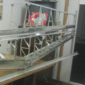
    If you look at my build log link at Homebuilt Aircraft you will find drawings and fabricated parts along with the failed load test.  
    https://www.homebuiltairplanes.com/forums/threads/aluminum-dragon.24732/post-708445

    Thank your for your help and interest 
  • don_bdon_b Member Posts: 106 ✭✭

    I see in your document that you are not using Frames and I see a lot tubes, maybe it is good to have a look at Frames.
     as many Part Studio's you need,
    The Tubes are the structural design I will look at frames but unless they are tubes it will not work
    The part geometry is developed in the assembly .....is there an advantage to breaking out a part into a new part studio
    I am not having problems with generation times yet because I have fiber optic internet. 
  • shawn_crockershawn_crocker Member, OS Professional Posts: 798 PRO
    @don_b I see. Very interesting. I will check out your website. It seems your sort of hybrid designing and building in parallel? When you say your first wing failed do you mean during a software test or during a shop test?
  • don_bdon_b Member Posts: 106 ✭✭
    sand bag test.......because I am a novice at aircraft stress analysis and the design structure was not a copy of an existing structure the safe engineering proof is to actually load it up......I had made some basic mistakes and it failed..... The new design is a truss design and I have better FEA software for truss design.....(I hope)  Which is why there are all those tubes and flat members going every which way. I am trying to have all the major stress loads accommodated with members in tension....
  • dirk_van_der_vaartdirk_van_der_vaart Member Posts: 533 ✭✭✭
    Have a look at the Learning center.
    https://learn.onshape.com/courses/frames-fundamentals

Sign In or Register to comment.