Welcome to the Onshape forum! Ask questions and join in the discussions about everything Onshape.

First time visiting? Here are some places to start:
  1. Looking for a certain topic? Check out the categories filter or use Search (upper right).
  2. Need support? Ask a question to our Community Support category.
  3. Please submit support tickets for bugs but you can request improvements in the Product Feedback category.
  4. Be respectful, on topic and if you see a problem, Flag it.

If you would like to contact our Community Manager personally, feel free to send a private message or an email.

Importing .stp / .step file appears only as one Surface. How to transform to an Onshape Part

DscheyDschey Member Posts: 8 ✭✭
edited February 2019 in Community Support
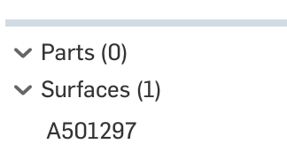
When importing a .stp or .step file it shows up in a Part Studio only as one "Surface" in the lower left area. But I need one solid "Part" for editing it e.g. removing parts of the geometry. I have tried various things link converting to solid via Freecad or importing in a different format. Nothing worked. Is there a specific function or workaround that I have missed? Any ideas much appreciated.
Answers

  • NeilCookeNeilCooke Moderator, Onshape Employees Posts: 5,674
    This usually means that the step file is either a) incomplete, b) poor quality, c) has edges that don’t knit together to make a solid. If you can find where the gaps are you can add surfaces and then use Enclose. Also, try changing the settings from the originating system or try a different format (Parasolid is best). I realise you might have downloaded this file and therefore cannot do much with it, but if the file is bad there’s not much we can do with it. 
    Senior Director, Technical Services, EMEAI
  • bruce_williamsbruce_williams Member, Developers Posts: 842 EDU
    @NeilCooke

    We receive files from many different customers and systems (Catia, Rhino, SW, SolidEdge, Autocad, etc.) and 'non-solid' files are a constant issue for us.

    I know getting a quality file is best.  However,  many times we are told that is all we will get.   Do you have or could you put on a webinar showing tips & trick for repairing files?   Working with Onshape to find holes, creating 3D curves, surfacing, knitting, etc. would be helpful.  
    www.accuratepattern.com
  • Jake_RosenfeldJake_Rosenfeld Moderator, Onshape Employees, Developers Posts: 1,646
  • bruce_williamsbruce_williams Member, Developers Posts: 842 EDU
    @Jake_Rosenfeld thanks for that FS it does help find problem edges and on an example like that it is easily repaired.  However on complex parts I am failing to figure how to repair to 'water tight' solid.  Try using all tools I can think of - thicken, fill, FS extend surface, delete/replace face, bridge curve, 3d spline, etc...    Maybe I am missing something...  SW's fix routines generally succeed so we continue to use that.
    www.accuratepattern.com
  • Jake_RosenfeldJake_Rosenfeld Moderator, Onshape Employees, Developers Posts: 1,646
    @bruce_williams

    My first reaction is to use fill here, do you have a recent example of a difficult case? 

    @philip_thomas is probably the most versed with issues like this.
    Jake Rosenfeld - Modeling Team
  • bruce_williamsbruce_williams Member, Developers Posts: 842 EDU
    Unfortunately, the current problem job may not be shared.  I will come back to this on the next one that is not confidential.

    www.accuratepattern.com
  • philip_thomasphilip_thomas Member, Moderator, Onshape Employees, Developers Posts: 1,381
    Gentlemen - this is a common problem in CAD and unfortunately, there is no 'magic' solution.
    Most of the time, it's not worth the effort.
    Sometimes however, there are just a few missing faces - in those situations, the fill tool and other surfacing tools will enable you to form a watertight solid (Onshape will automatically sew a closed volume into a part). 
    Where two edges won't sew, you will likely have to delete one of the adjacent faces and create a new face.
    This is a royal pain in most cad systems and the least effort is always working with the supplier to get a good step or parasolid file.
    Philip Thomas - Onshape
  • DscheyDschey Member Posts: 8 ✭✭
    --- issue solved ---

    Many thanks @all for your recommendations. Actually we could analyze the original Autodesk Inventor file and it showed no issues. Exporting as .stp, .x_t or .x_b worked without any problems or errors. However, importing the newly created .stp again did not show up as solid, only as one surface in the Onshape part.

    But, importing the .
    x_t or .x_b worked! It now shows up as solid part and I can fully work with it, i.e. I can add or remove parts. So I'd recommend users with similar problems to ask for CAD file export in the .x_t or .x_b format and then import these.
  • NeilCookeNeilCooke Moderator, Onshape Employees Posts: 5,674
    @Dschey - thank you for following up with your findings. A Parasolid file (.x_t, .x_b) will always have the best fidelity since Onshape uses the Parasolid kernel. However, Inventor does not - it uses its own modified flavour of the ACIS kernel (.sat). So in this case it does not make sense why .x_t came in better than .stp since Inventor had to a conversion for both. Welcome to the shady world of CAD file translations!

    Onshape will read native Inventor .ipt files. Did you try that?
    Senior Director, Technical Services, EMEAI
  • DscheyDschey Member Posts: 8 ✭✭
    NeilCooke said:
    @Dschey - thank you for following up with your findings. A Parasolid file (.x_t, .x_b) will always have the best fidelity since Onshape uses the Parasolid kernel. However, Inventor does not - it uses its own modified flavour of the ACIS kernel (.sat). So in this case it does not make sense why .x_t came in better than .stp since Inventor had to a conversion for both. Welcome to the shady world of CAD file translations!

    Onshape will read native Inventor .ipt files. Did you try that?
    I tried importing the .ipt file. It did not work. Onshape message when importing: "..failed to translate: Imported file contains no translatable geometry". Tried two different .ipt files. So if the import of native .ipt usually should work, then probably a specific CAD issue. However, we could not figure out what the problem with the AI CAD is.
Sign In or Register to comment.