Welcome to the Onshape forum! Ask questions and join in the discussions about everything Onshape.
First time visiting? Here are some places to start:- Looking for a certain topic? Check out the categories filter or use Search (upper right).
- Need support? Ask a question to our Community Support category.
- Please submit support tickets for bugs but you can request improvements in the Product Feedback category.
- Be respectful, on topic and if you see a problem, Flag it.
If you would like to contact our Community Manager personally, feel free to send a private message or an email.
Bridging Curve Weirdness
 S1mon
Member Posts: 3,812 PRO
While Bridging Curves are useful, the behavior for curvature continuous curves is a little strange. A while ago I copied the standard code for Bridging curve and made some updates to the math to improve the control polygon layout. Let me go through an example...
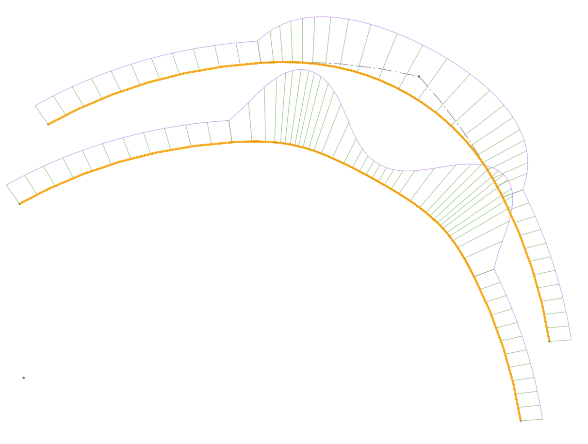
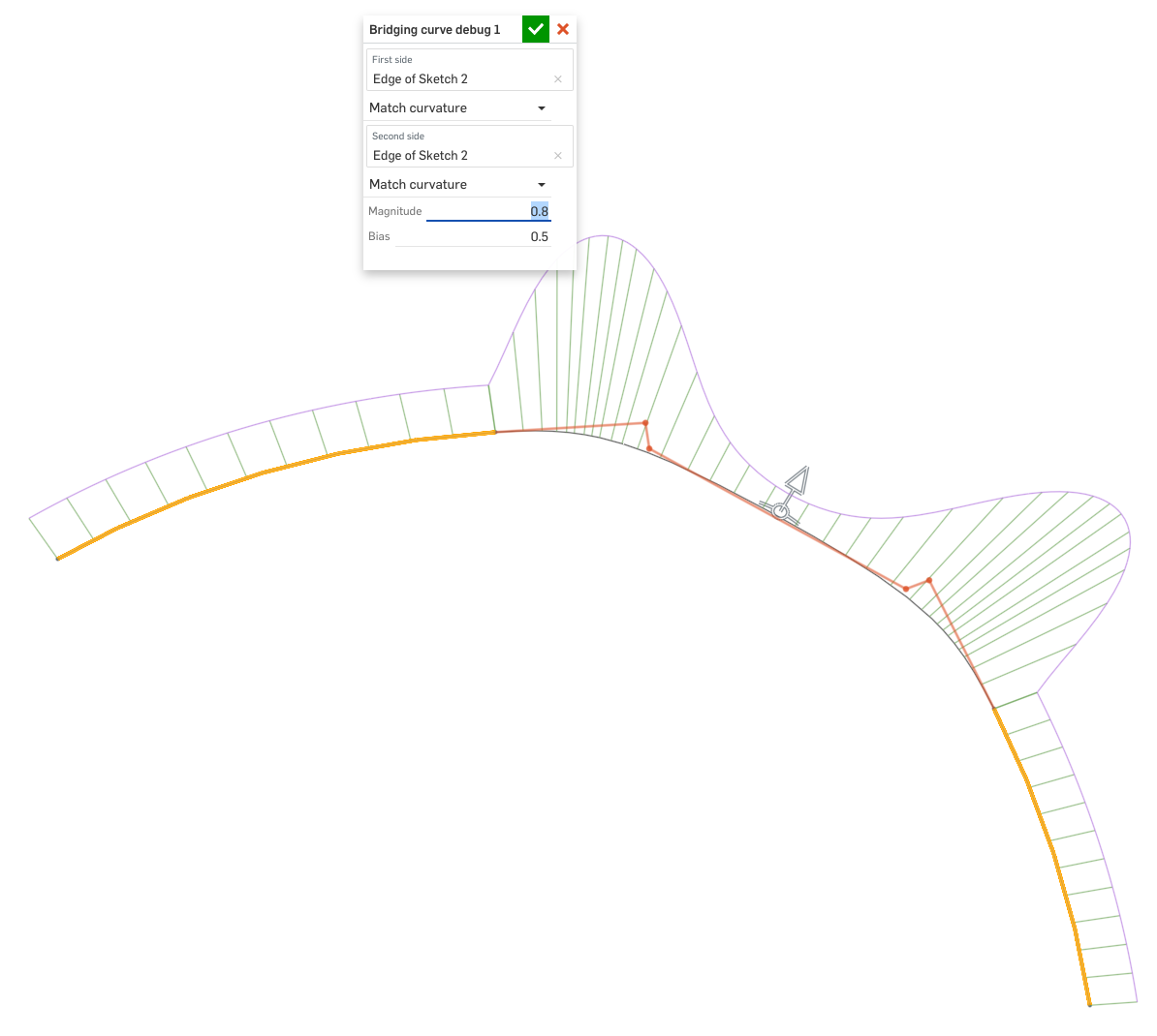
My version is the upper one, the lower is the standard. Both are on parallel planes with the same radius arcs as inputs to the Bridging Curves. Both have the magnitude at 1.0 and the bias at 0.5. Here's mine in edit mode, which has the control polygon shown in red.
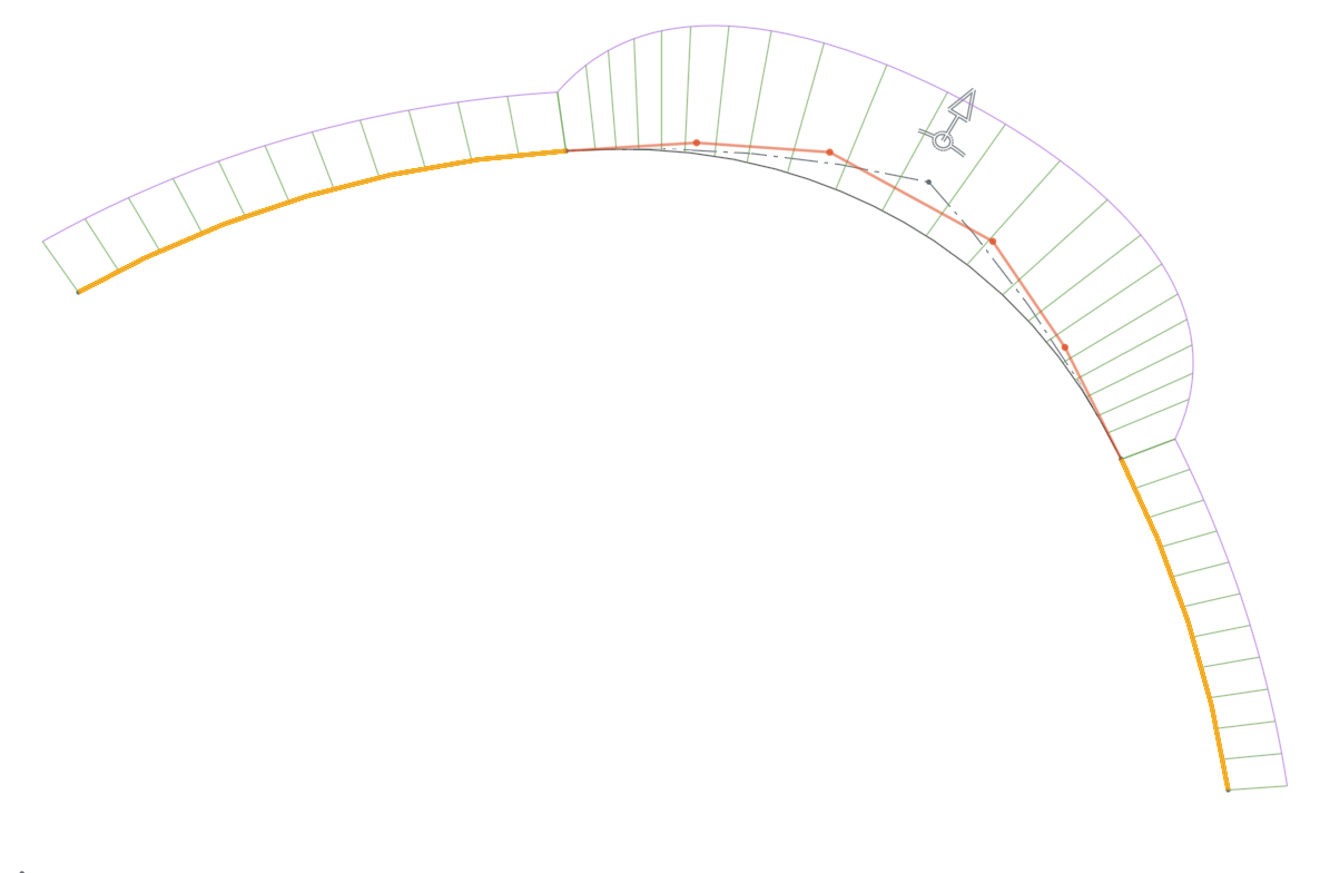
Here's the standard Bridging Curve, with added debug control polygon:
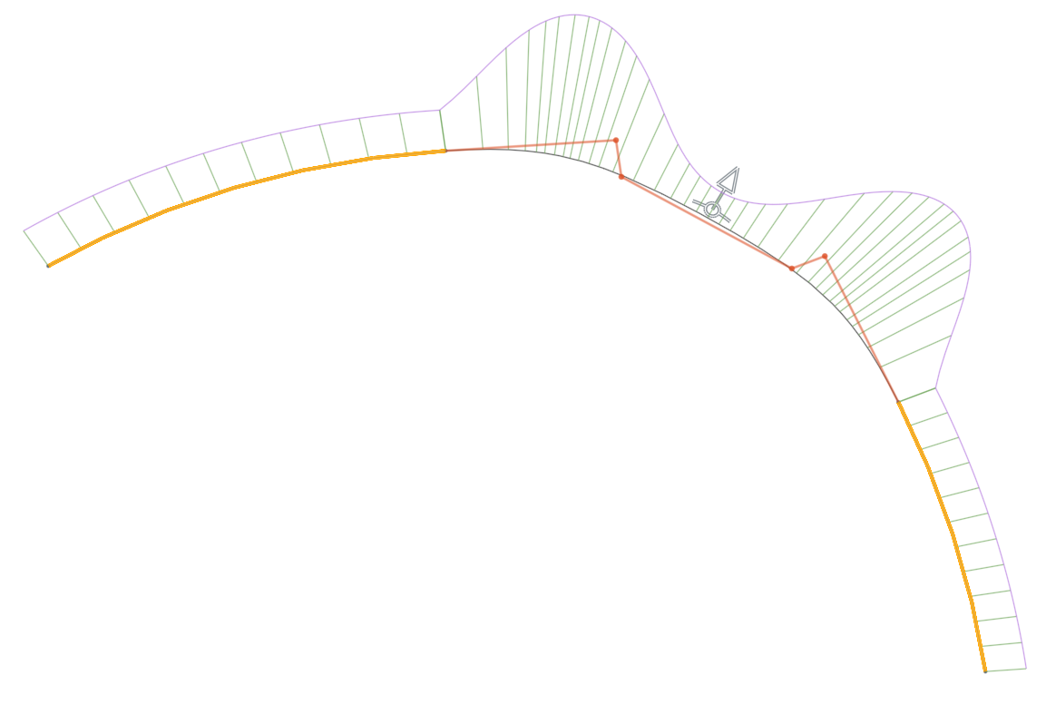
While the arrangement of the CVs is technically correct to give G2 at each end in the standard version, the shape and parameterization of the curve is not best practice. See Alias's Golden Rules for some great guides around managing and manipulating CVs on curves. The above CV layout violates the "spacing" and "distance" guidance from Alias.
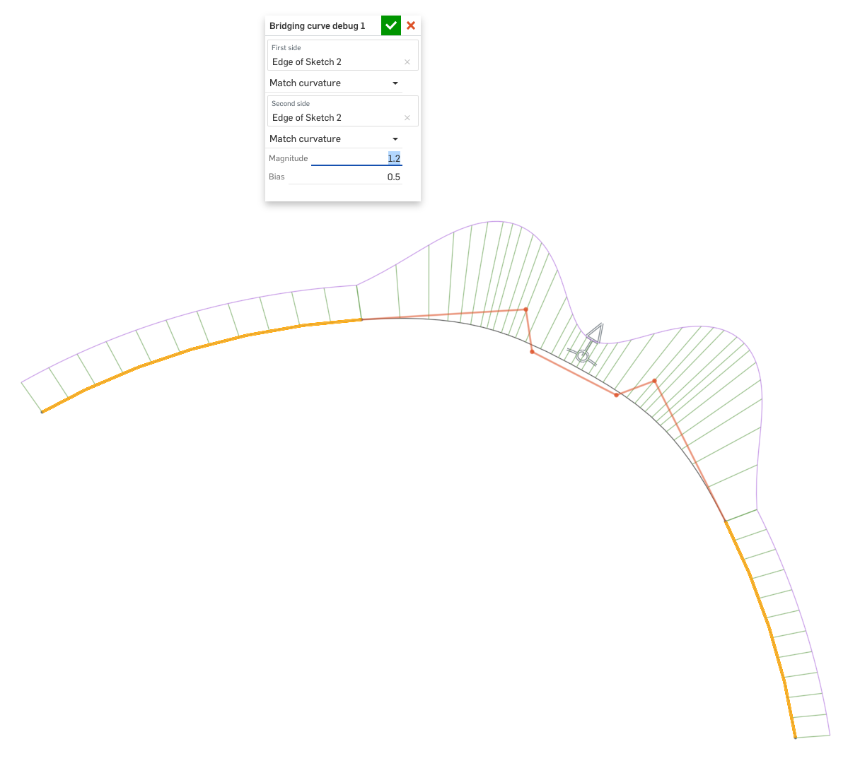
With my version of the math, and a little tweaking of the magnitude (1.0->1.2), I can easily get something that visually approaches G3 at both ends:
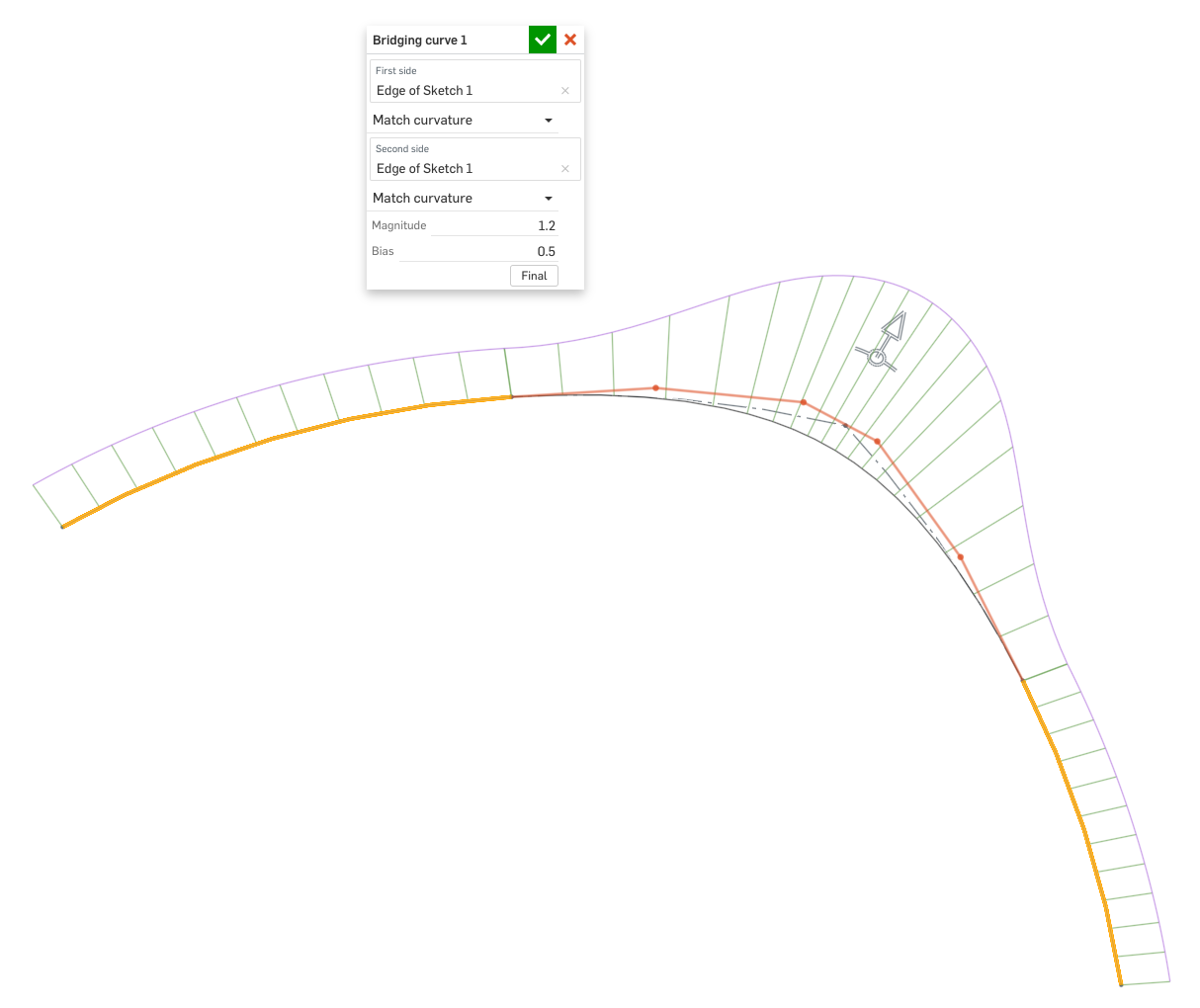
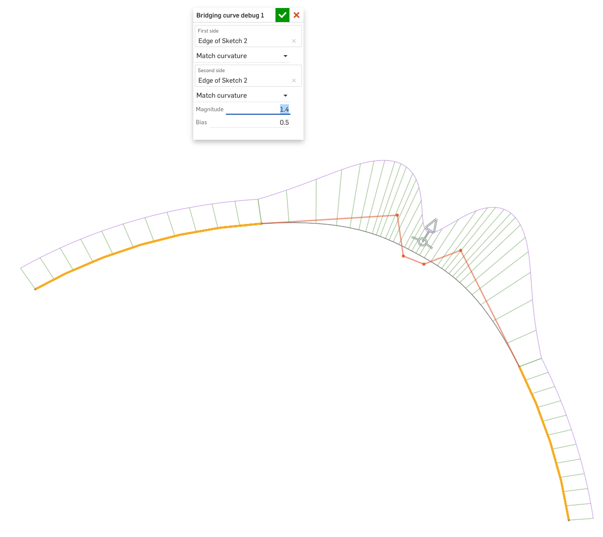
No amount of tweaking of the standard version will result in something with this smoothness. In fact it just gets lumpier when I adjust the magnitude in either direction:
While it would be weird to fix this issue in the standard code since it would change the geometry of existing models, it really seems like this should be rectified somehow. I'd also like to make Bridging curves a little more general by doing some of the following:

My version is the upper one, the lower is the standard. Both are on parallel planes with the same radius arcs as inputs to the Bridging Curves. Both have the magnitude at 1.0 and the bias at 0.5. Here's mine in edit mode, which has the control polygon shown in red.

Here's the standard Bridging Curve, with added debug control polygon:

While the arrangement of the CVs is technically correct to give G2 at each end in the standard version, the shape and parameterization of the curve is not best practice. See Alias's Golden Rules for some great guides around managing and manipulating CVs on curves. The above CV layout violates the "spacing" and "distance" guidance from Alias.
With my version of the math, and a little tweaking of the magnitude (1.0->1.2), I can easily get something that visually approaches G3 at both ends:

No amount of tweaking of the standard version will result in something with this smoothness. In fact it just gets lumpier when I adjust the magnitude in either direction:


While it would be weird to fix this issue in the standard code since it would change the geometry of existing models, it really seems like this should be rectified somehow. I'd also like to make Bridging curves a little more general by doing some of the following:
- Add G3 options at either end
- Allow the user to increase or decrease the degree within the limits of what's possible given the current tangency constraints
- Add a "roundness" or some other parameter for the higher degree curves to control the shape of the middle of the curve, while keeping the controls simple and parametric
- Make it easy to flip the tangent direction at either end
- Specify end points and tangent directions separately, similar to how Creo's style curves work
- Have an option for a mirror tangency, similar to Creo's style curves
- Allow moving the endpoints away from a vertex based on a percentage of an edge/curve or an absolute distance from the starting vertex
Simon Gatrall | Product Development Specialist | Open For Work
Tagged:
3
Comments
Thank you for the detailed analysis and the Alias link. We've done something rather naive there and will have to address it soon. We have a mechanism for fixing geometry for new features only without breaking the existing ones, so we will fix it. Thank you for the list of improvements as well.
I've avoided using the bridging curve feature because of this lack of control, and would love it otherwise. If you ever feel like making your modification public, let me know. I'd add it to my toolbar for sure.
The Onsherpa | Reach peak Onshape productivity
www.theonsherpa.com
I'm happy to share my code tweaks with Onshape (I'm not quite ready to make it a public FeatureScript), and also very happy to have any detailed discussions about potential improvements.
Simon Gatrall | Product Development Specialist | Open For Work
The immediate issue with our bridging curve is that we were making the second segment of the control polygon always perpendicular to the first, and that's not a good heuristic in general.
Even for G1-G1 bridging curves, we could make better defaults.
Apparently there are still papers being published on this problem. For instance:
2011 on G1-G1 https://www.fmf.uni-lj.si/~jaklicg/papers/curvatureAMC.pdf
2019 on G2-G2 https://www.sciencedirect.com/science/article/pii/S0010448518304305
Both papers define a linearized energy and optimize it analytically. And in both cases, the solution becomes singular as the tangent vectors become parallel, making them unsuitable in some of the cases we care about.
I tried a few things and the best I found so far is a simple heuristic -- in my testing, it works well for G1-G1 and does ok for G2-G2 (although there's definitely room for improvement there -- but adjusting magnitude and bias helps). Here it is: https://cad.onshape.com/documents/41d27a6e2dca6c481aa953e8/v/7530f70d4f5c7b84605a38af/e/f574b4e850f22dabc3e30e5c
It's just for gathering feedback and experimenting, not production use! I will make changes to our standard bridging curve once I am satisfied with the approach.
@S1mon @Evan_Reese and others, where do you think this is on a scale of 1-10 (where what we have today is 2 and what you'd ideally want is a 10) in terms of default (magnitude 1, bias 0.5) control point placement? I get the other requested improvements, but I want to try to get this reasonable first.
From some quick evaluation, it seems like you're heading in the right direction. One of the things I was trying to do in my version was make it so that if you switch from degree-3 to 4 to 5, the center of the curve doesn't move too much, and the spacing of the CVs is relatively even when the bias is at 0.5. You seem to have gotten that to work.
On thing that I might question is the G0G2 case, when the bias is shifted off of 0.5, I would like to see something with some acceleration between the 3 lengths of the polygon.
I'll have some more feedback on Monday. Cool to see the work in progress!
Simon Gatrall | Product Development Specialist | Open For Work
I'm going to add feedback as I think of it...
Another metric for a good bridging curve is the behavior for a very simple and very common case (for designers) - replacing a tangent arc corner. Starting with two perpendicular lines with an equal gap, I would expect to get something approximating an arc if both ends are set to tangent and the magnitude is 1.0. Instead I get this (arc shown for comparison):
If you're looking for a place to start with the lengths of the first and last control polygon length, a slightly better version would be to have them be 0.5 of the radius here. Or you could start with 0.551915024494 which gives less that a 2% error (see this).
Another weirdness with these input lines - if I match tangent on one side and leave position on the other the shape at magnitude=1 makes perfect sense:
But when I change the tangent to curvature, the shape changes radically:
I might expect something more like this (but instead of 0.742 it would say 1.0):
When we get to G2G2 case the prototype version looks like this:
In my version I did this:
I think I flattened things out too much in the middle, but the goal was to get it closer to being an arc at Magnitude = 1.0.
I looked at what Rhino does with their Blend Curve (similar to Onshape's bridge curve, except it goes up to G4, and each CV is editable). Their default "magnitude" is closer to what you've got, but they don't have a magnitude/bias control, and depending on the order you change the continuity constraints you get different results - which strikes me as bad behavior.
Here's a G2G2 version in Rhino which is closer to an ideal version of what I might want to see at Magnitude = 1.0:
I've manually adjusted the CVs from the default positions after choosing Curvature-Curvature. The middle of the curve is "arc-like", the parameterization seems Ok, and the acceleration in/out of the arc is not too abrupt.
Another comparison to keep in mind, here's curvature continuous fillet between the prototype and my version of the Bridging Curve:
Honestly this is the worst of the bunch. The parameterization is bunched up at the ends and the middle and the shape is lumpy. About the only thing going for it is that it's close to an arc, and you get all the functionality of filleting, but the shape is not ideal at all. I sometimes use them with the magnitude dialed up a little (say 0.6) to get something which isn't so lumpy, but they don't really serve the purpose that I want at all.
Simon Gatrall | Product Development Specialist | Open For Work
That's good to know. I've usually assumed that curvature combs on any CAD system were spaced based on parameterization. It makes me very nervous to see things bunched up like that, since bad parameterization can cause all kinds of pain downstream. (If things are too bunched at an end, and then you need to extend it, you often get unwanted results).
It's great that the outside curve of the combs is based on an adaptive sample, but it would be nice if the combs themselves were spaced based on the parameterization. If that's not possible, it would be nice if there was some way to quickly judge the parameterization of a surface that Onshape generates. With the exception of fill surface, I don't think anything previews with UV isocurves. One thing I really like about Rhino is how it displays the Isocurves on surfaces. I sometimes export from Onshape just to see these curves. They tell me how "heavy" a surface is, and if there are any obvious defects in the parameterization of a loft.
Simon Gatrall | Product Development Specialist | Open For Work
I'm doing some more experiments with the prototype. When the inputs are two curves - in this case one is twice the radius of the other - the behavior is quite good. Without tweaking the bias, I can get something which approaches G3G3, just by tweaking the magnitude. To me this is great.
The default behavior at G1G1 is also much improved from the STD version.
Proto:
STD:
One thing I've been noticing is that the bias adjustment is "detented" into certain values. Of course you can edit the number directly, but if you're trying to dial things in visually, the jumps in value are way too large. Duh, I just realized that "Shift" allows for very fine Bias adjustment without the detented values. That isn't in the Bridging Curve help page, but maybe it's covered somewhere else?
Simon Gatrall | Product Development Specialist | Open For Work
Thanks! -- I think I have enough to work with for the time being to improve the G2 cases -- I don't want you to invest time into more experiments with the G2 behavior of the prototype, since I'm planning to change it.
I didn't know about the shift thing -- was going to debug the jumpiness (since I saw it too).
Once the feature gets updated I'll probably co-opt the algorithm for placing the CVs for each continuity type since. I've been working on adding a control point spline option to Freeform Spline. I didn't even realize there was a bSplineCurve() function till this thread.
The Onsherpa | Reach peak Onshape productivity
www.theonsherpa.com
I know you said you had enough work to do... but here's one that is concerning:
My version of this situation is not perfect either, but it doesn't invert the curvature:
One of the things that was really good about the original code is how it develops the "speed" per side based on a degree-3 approximation first. That avoids the situation in the first screenshot in this post.
Simon Gatrall | Product Development Specialist | Open For Work
Seems like the new curves have better default values for magnitude 1. But, for those of us who just drag things around, there's not much changing here? I agree magnitude 1 should look better. But, I can make the old curves look like the new proposed curves by dragging manipulators?
createBezierCurve(), I like this visual feedback
If speed is complex to compute, should we have user control of it? Possibly multiple manulators to control the array of speeds? Is that to much?
@S1mon thanks for your input about class A surfacing. I'm going to pay more attention to curvature combs in the future.
I feel bad. I haven't had much time to really properly review this. My initial reactions were:
There are many applications where I would commonly use multiple bridging curves and essentially copy the values to get a similar feel. With 4 numbers it's more work to copy the feel to another curve, but still possible.
There are many features I'd love to see added to this next generation version, but maybe the biggest bang for the buck would be to allow the separation of the end vertex from the tangent/curvature direction. WOW it already does this!!
I would include a flip option to both ends to control the positive/negative direction of the tangent vector.
Simon Gatrall | Product Development Specialist | Open For Work
At this point, my plan is to "productize" this, replacing our current bridging curve. Existing bridging curves will maintain existing controls and behavior, while new ones will be like the custom feature.
Thanks for adding the flip option! (Please consider this for lofts too)
I really really value having the control polygon be visible, but I wonder if there are good options and precedents in other parts of Onshape for a color or line style which seems less strong than the dark blue. In many other systems the control polygon is a lighter or dotted line. When you are editing a curve the control polygon and the curvature plots are hugely useful and critical, but I always have to remind myself to look at the curve itself. With 4 large arrows and the blue line, I find myself too focused on them visually. They need to be there, and the arrows need to be easy to select including on mobile, but maybe there's a way to make it a little less distracting? Even though the control points can only slide along specific vectors and maintain G1 or G2, it's not clear to me that the manipulator needs to be an arrow. Maybe just a circle?
Nine times out of ten, when I create or edit a bridging curve, I'm going to turn on the control points, and show curvature for the bridging curve and the curves it's connected to. This adds a bunch of clicks. I recognize not everyone is going to do this, but I wish it took fewer clicks to get there.
Rhino (and I assume Alias and others) have easy ways to optionally drag both tangents (or curvature) weights symmetrically. This is a common thing. We had this in the previous official version with the magnitude. Perhaps there is a way with holding shift and dragging one manipulator to adjust both ends at the same time? https://docs.mcneel.com/rhino/7/help/en-us/commands/blendcrv.htm
Will there be an easy way to update an old bridging curve to the new version?
Am I being too greedy if I ask when do we get G3 and G4?
Simon Gatrall | Product Development Specialist | Open For Work
Another thought about the 4 parameters and editing. What if the tool starts with the same magnitude/bias manipulator as the released version, but then you can click on the "edit control points" to move individual points. I would still just use the same 4 values (for G2G2), but give the user the option of a simple or more complex manipulation.
Simon Gatrall | Product Development Specialist | Open For Work
I can't promise anything until functionality goes through our UX and QA, but I hope to make it possible to update existing bridging curves to the new version, and that same mechanism should also allow you to go back to the old implementation if you want the symmetric magnitude drag.
I'm curious how the Bridging Curve update is going. Anything new you'd like people to beta test?
Simon Gatrall | Product Development Specialist | Open For Work
I'm very glad to see the latest update.
The only thing that's a little disappointing is that switching "method" from "magnitude/bias" to "control points" completely changes the shape of the curve. I can see why it might not be possible to go the other way without having to change the shape, but "control points" should be able to represent anything that "magnitude/bias" can do. I would assume any future improvement with this would be backwards compatible.
Simon Gatrall | Product Development Specialist | Open For Work