Welcome to the Onshape forum! Ask questions and join in the discussions about everything Onshape.
First time visiting? Here are some places to start:- Looking for a certain topic? Check out the categories filter or use Search (upper right).
- Need support? Ask a question to our Community Support category.
- Please submit support tickets for bugs but you can request improvements in the Product Feedback category.
- Be respectful, on topic and if you see a problem, Flag it.
If you would like to contact our Community Manager personally, feel free to send a private message or an email.
Non-prismatic stuff
 billy2
Member, OS Professional, Mentor, Developers, User Group Leader Posts: 2,119 PRO
billy2
Member, OS Professional, Mentor, Developers, User Group Leader Posts: 2,119 PRO
One of the biggest complaints about solid modeling is it's prismatic nature (everything looks like an extrusion).
It doesn't have to be this way:

Organic shapes take a little more effort and requires you to think 3 steps ahead. It's not uncommon to to create a surface to create yet another surface and then make your shape.
I had to re-loft this face because Onshape won't allow solid/surface operations. There's no reason I shouldn't have access to this face even though it's part a a b-rep. Let's get over this and move on:

Move face will offset a face if it's a face, otherwise it will create solid offset. Don't worry I've already requested that this be changed:

So I split the face and translate it down to position the highlighted curve. It may seem like a lot of work just to get a curve in space, but I want it controlled by the bodies' original shape and some other little controls to help the upcoming loft:

Why didn't I just create a plane, offset a projected curve and then trim that curve? Could have.
Mirror control surface to opposite side, and adding a center sketch. Create my loft. All operations in Onshape require full sheets, meaning that I can't define the right then mirror to the left and knit together for a cut. I've asked for this. We need knitting. Loft a cool shape that's highly controlled with behaving curves:

All cad systems have a function called replace face. I never use it because my mind doesn't think that way. Most people build by adding. Replace face builds by subtracting which isn't 1st nature to most people. Replace one face with another:

Ok so now I have a simi-controlled organic shape. How would you extrude this? I suppose you could extrude up to this face, but you'll still need to construction the controlled face to extrude up to. Also, I'm updating an existing design so extruding upto face isn't in my current workflow. Organic stuff inside Onshape:

Typically I'd want more control over the organic shape. This is just a simple example of making something look cool. After all it has to look good, who cares if it actually works.
It doesn't have to be this way:
Organic shapes take a little more effort and requires you to think 3 steps ahead. It's not uncommon to to create a surface to create yet another surface and then make your shape.
I had to re-loft this face because Onshape won't allow solid/surface operations. There's no reason I shouldn't have access to this face even though it's part a a b-rep. Let's get over this and move on:
Move face will offset a face if it's a face, otherwise it will create solid offset. Don't worry I've already requested that this be changed:
So I split the face and translate it down to position the highlighted curve. It may seem like a lot of work just to get a curve in space, but I want it controlled by the bodies' original shape and some other little controls to help the upcoming loft:
Why didn't I just create a plane, offset a projected curve and then trim that curve? Could have.
Mirror control surface to opposite side, and adding a center sketch. Create my loft. All operations in Onshape require full sheets, meaning that I can't define the right then mirror to the left and knit together for a cut. I've asked for this. We need knitting. Loft a cool shape that's highly controlled with behaving curves:
All cad systems have a function called replace face. I never use it because my mind doesn't think that way. Most people build by adding. Replace face builds by subtracting which isn't 1st nature to most people. Replace one face with another:
Ok so now I have a simi-controlled organic shape. How would you extrude this? I suppose you could extrude up to this face, but you'll still need to construction the controlled face to extrude up to. Also, I'm updating an existing design so extruding upto face isn't in my current workflow. Organic stuff inside Onshape:
Typically I'd want more control over the organic shape. This is just a simple example of making something look cool. After all it has to look good, who cares if it actually works.
Tagged:
1
Comments
Floppy motorcycle turn signals
Printing out a new LED set of lights:
From the outside it looks easy. The LED's are derived parts and I've included negative space in the derived part definition. What? I import the LED's and position them, each has a body that I use to boolean out the mounting configuration. I should write up a blog post about derived components, it's working really well these days and could redefine library components for all CAD systems. Bring over the mounting geometry with the library part.
I'm hoping I can solder all the leads together without melting the printed plastic housing. I may tie the leads together using a ferrell to help hold them together mechanically. After soldering I'll pot everything with some epoxy to protect against the elements.
My goal is to make a light that'll last longer than the motorcycle. Remember there are Harley's from the 1914's so these lights will have to last more than 100 years. I'm using ASA print material which has a UV inhibitor, who knows what the plastic will look like a 100 years.
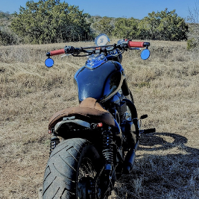
FZ09 without floppy turn signals:
Because these are running lights & turning lights, I'll need to add 2 resistors & 2 diodes. Also I'm not running a regulator and will rely on motorcycles regulator. Planning on 14 volts. I know they'll dim when bike is shut off but who cares?
I'm not happy with the shape as it sinks in like a kidney bean casting off the wrong light reflection. Even though it's a crappy printed part, it still bugs me.
I only had red leds, the amber ones are on order. It's illegal to have a red light facing forward on a street vehicle, and more important, it's just not a good idea.
So where did the problem occur?
I didn't use the definition explained above to define curvature and moved to a more advanced method. I used qty 2 2-noded splines with a center tangent constrained. Turns out this gives me angular control over center nodes and makes for a bitch'n curve:
In a loft, you can't pick compound curves for U or V definitions (selection manager). Those 2 spline curves, I want the loft to treat them as one curve, can't do it.
Not having a fit spline, I'll make my own. In a sketch I created many line segment attached to the splines and set them to equal length. Now where there is greater curvature, the cordial height from the original spline to the line segment is too much so I subdivide those areas by adding more line segments. More curvature demands more line segments and ultimately more vertices. It's just the way it is.
With all these line segments I now use Ilya's 3D spline and recreate a new spline:
So you can see the curves dancing through Euclidean space and they're close.
But the surface, I don't like it:
Now if I get some time, I'll take Ilya's 3D spline and write a feature script that'll do the same algorithm that I manually performed. Checking the cordial height half way along each line segment and shortening the line segment length with a conditional statement if the cordial height grows too tall. I'll roll my own fit spline. You'll specify a tolerance which controls the difference between the line segment and the spline in turn producing more vertices around tight curvature and less in straighter portions. This is basically a fit spline algorithm.
So I tried this:
Then this:
I like this center inflection. See how the light shines off the body. Don't like the center dimple. I like this look better.
I've order my
-amber leds
-resistors
-diodes
And I've started another print job.
Here are 2 splines with a tangential constraint between them. I like this curve:
So I run Billy's Fit Spline which breaks curves down to a minimum of 50%:
By changing the tolerance, you get more definition:
You can turn off the scaffolding:
Make a loft using fit spline:
Make a change to the 2 splines:
And it propagates through:
That's just freak'n cool.
Onshape, Inc.
Fit spline is highlighted:
Twitter: @onshapetricks & @babart1977
Onshape, Inc.
Twitter: @onshapetricks & @babart1977
Thanks!