Welcome to the Onshape forum! Ask questions and join in the discussions about everything Onshape.
First time visiting? Here are some places to start:- Looking for a certain topic? Check out the categories filter or use Search (upper right).
- Need support? Ask a question to our Community Support category.
- Please submit support tickets for bugs but you can request improvements in the Product Feedback category.
- Be respectful, on topic and if you see a problem, Flag it.
If you would like to contact our Community Manager personally, feel free to send a private message or an email.
How do I position one oblong inside another oblong?
 bart_harris
Member Posts: 29 ✭
I have a small oblong that I would like to position in a big oblong, centred horizontally and offset to a fixed distance vertically. Can anyone help please?
I'm new to professional CAD and should probably take a course.
I'm new to professional CAD and should probably take a course.
Tagged:
0
Best Answers
-
 andrew_troup
Member, Mentor Posts: 1,585 ✭✭✭✭✭
I would add points near the two top horizontal lines, then use 'midpoint' constraints to place those points half way along those lines, then a 'vertical' constraint between the two points. I would dimension the width of each rectangle.
For the heightwise constraint I would dimension the height of each rectangle, and include either the 9mm or 27mm dimension to relate their heightwise position5 -
 brucebartlett
Member, OS Professional, Mentor, User Group Leader Posts: 2,148 PRO
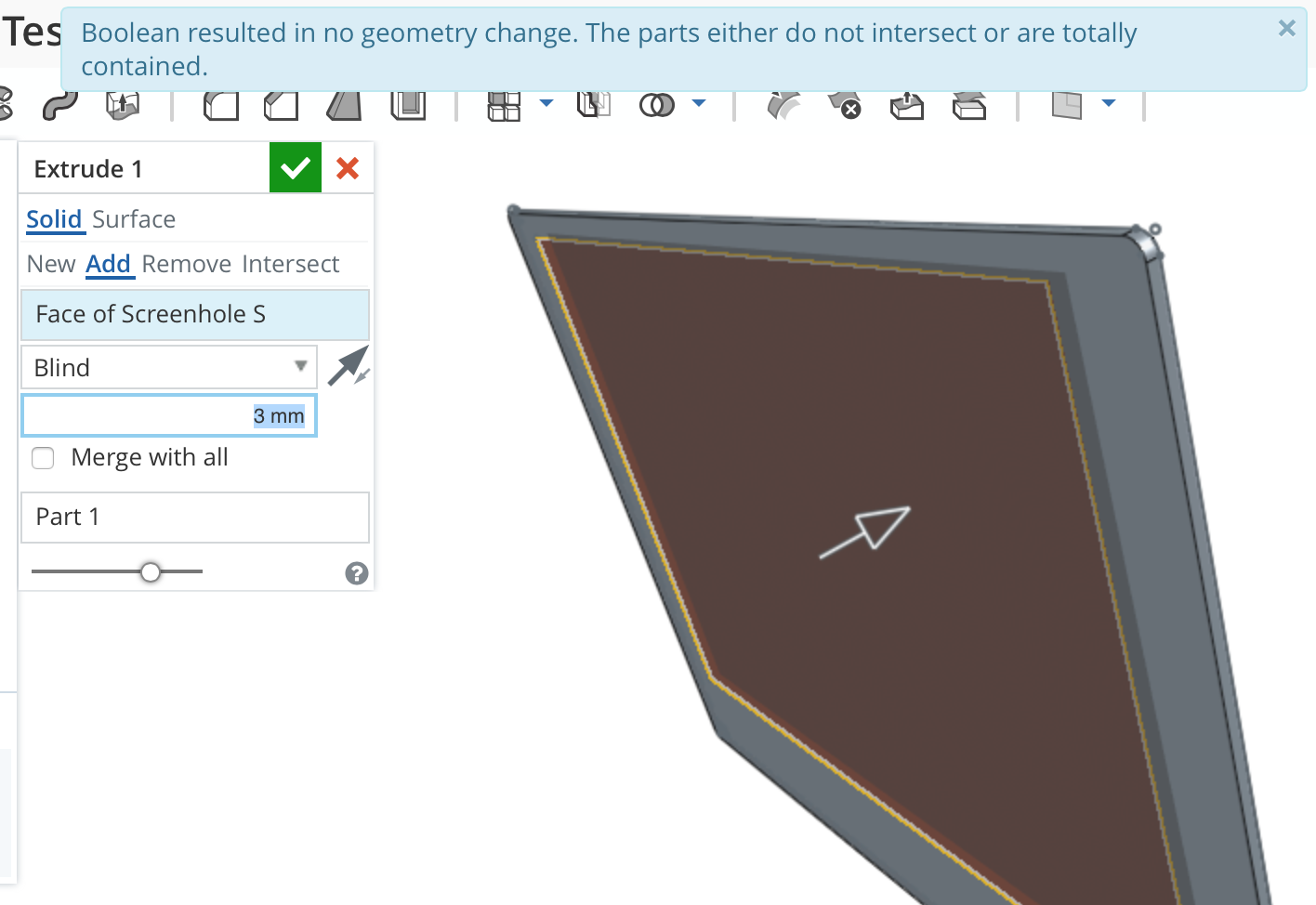
@Chris_Kaspian the Error message your seeing is because the extrude is going back into the existing solid and merging result in no change to the existing solid.Chris_Kaspian said:I'm trying to figure out what you're saying, Andrew_Troup, and will take a look as soon as I can. Thank you.
Coleman, the interior feature is a recess. I actually tried extruding it into my already extruded outer oblong but this resulted in the strangest error message I have ever encountered (see image). I was going to move onto this but clearly my intermediate knowledge of SketchUp is no match for professional software like Onshape...
Try change to New and you will see 2 parts in your list, Change to Remove and you see the hole cut-out. Maybe try playing with the different optios on the extrude dialogue, you will soon get the idea.
All so try changing the Blind to Though all, that will blow the hole right through everything.5 -
 jakeramsley
Member, Moderator, Onshape Employees, Developers, csevp Posts: 669
  1. Start with a well defined first sketch. I did a center point rectangle about the origin and made it 236mm x 174mm,
2. Start a second sketch and sketch the rectangle about where you want it to be. Start a construction line at the mid-point of the top line. Drag it so that it is perpendicular to the top line.

3. Select the end point of the line that isn't constrained and the top line of the other sketch. Make the point a midpoint of that line. The rectangles will now be centered about that line. Note: If you have filleted the line so that the midpoint isn't the part you want centered, you can create points that are coincident with the vertical and horizontal edges. From here if you select the two points and the end of the line, you can apply a midpoint between all three and constrain the line that way.
4. Add your dimensions to the rectangle as well as the construction line to get the offset.
Jake RamsleyDirector of Quality Engineering & Release Manager onshape.com5 -
 3dcad
Member, OS Professional, Mentor Posts: 2,476 PRO
-
 3dcad
Member, OS Professional, Mentor Posts: 2,476 PRO
Just make your own copy and click edit for sketch and same to extrude.
What I did was a sketch with both rectangles in it and extrude for that whole sketch.//rami5
Answers
For the heightwise constraint I would dimension the height of each rectangle, and include either the 9mm or 27mm dimension to relate their heightwise position
If a separate part...how much clearance between the two?
Coleman, the interior feature is a recess. I actually tried extruding it into my already extruded outer oblong but this resulted in the strangest error message I have ever encountered (see image). I was going to move onto this but clearly my intermediate knowledge of SketchUp is no match for professional software like Onshape...
1. Create outer shape sketch and extrude to body thickness.
2. Create inner sketch on the top face of outer and extrude with option 'Remove' (flip direction if needed).
The best way to get help is to make a public copy and share link so others can actually see your model.
Try change to New and you will see 2 parts in your list, Change to Remove and you see the hole cut-out. Maybe try playing with the different optios on the extrude dialogue, you will soon get the idea.
All so try changing the Blind to Though all, that will blow the hole right through everything.
Twitter: @onshapetricks & @babart1977
I couldn't make it work initially because I made the oblongs separate sketches but now i've figured it out using just on sketch.
Thank you for this but as I explained in my reply above, I could not see how to align the inner rectangle if it was a separate sketch. Any ideas?
2. Start a second sketch and sketch the rectangle about where you want it to be. Start a construction line at the mid-point of the top line. Drag it so that it is perpendicular to the top line.
3. Select the end point of the line that isn't constrained and the top line of the other sketch. Make the point a midpoint of that line. The rectangles will now be centered about that line. Note: If you have filleted the line so that the midpoint isn't the part you want centered, you can create points that are coincident with the vertical and horizontal edges. From here if you select the two points and the end of the line, you can apply a midpoint between all three and constrain the line that way.
4. Add your dimensions to the rectangle as well as the construction line to get the offset.
You need to edit the extrude distance of the inner rectangle to "Through"
No need to hide construction lines; they do not confuse Onshape (it ignores them when using the sketch)
If they confuse you, simply hide the entire sketch by clicking to the right of the sketch entry in the feature tree. An icon of an eye with a diagonal slash denotes a hidden sketch.
Also, why would I delete an entire sketch if it's the only thing I have on the page?
Is this what you need?
https://cad.onshape.com/documents/f3902dfa90e641629cddc21d/w/17311692521a42d5afeeeb06/e/1fee2feb39f9479f9d79d5c3
What I did was a sketch with both rectangles in it and extrude for that whole sketch.