Welcome to the Onshape forum! Ask questions and join in the discussions about everything Onshape.
First time visiting? Here are some places to start:- Looking for a certain topic? Check out the categories filter or use Search (upper right).
- Need support? Ask a question to our Community Support category.
- Please submit support tickets for bugs but you can request improvements in the Product Feedback category.
- Be respectful, on topic and if you see a problem, Flag it.
If you would like to contact our Community Manager personally, feel free to send a private message or an email.
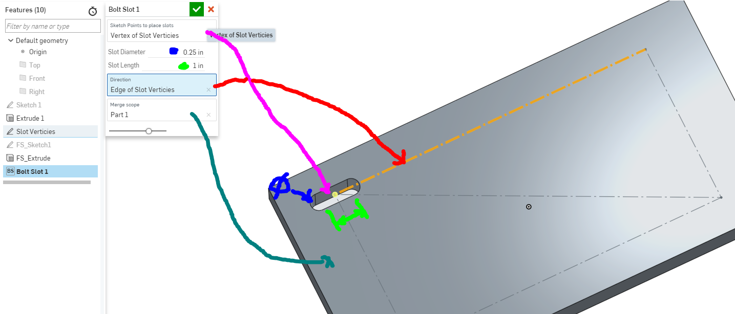
Can someone make / Teach me how to make this simple script?
 john_mcclary
Member, Developers Posts: 4,040 PRO
I HATE the FS "tutorial" and "documentation". Tutorial is too specific to one feature script. and the documentation has no example snippets to learn from.
I cant even create a sketch plane. All I've managed to do is add a hole in my closet door...
Can someone show me how to accomplish this? OR just do it for me and I'll try and learn from it?
I use slots all the time and drawing them is very tedious. I've been trying to make this simple thing since I first heard of FS.
I just keep going backwards.
I just want to select a direction, and points, then a slot will be drawn at every point with the same direction.
It should behave like hole feature.
Crap, looks like the i forgot to show an end type (Through all, blind, etc)

0
Best Answers
-
 emagdalenaC2i
Member, Developers, Channel partner Posts: 864 ✭✭✭✭✭
You do not need to create a new macro in FeatureScript ... ;-)You can simply use the existing Point Pattern FeatureScript https://cad.onshape.com/documents/4402eb26f362f4ac8bd389e6/w/829e986ca2d54ef161ace1dc/e/1f020f28cc5b70ff3c5af1d9
 Un saludo,
Eduardo Magdalena C2i Change 2 improve ☑ ¿Por qué no organizamos una reunión online?
Partner de PTC - Onshape Averigua a quién conocemos en común7 -
 Jake_Rosenfeld
Moderator, Onshape Employees, Developers Posts: 1,646
  Hi @john_mcclary
Sorry you're having trouble! More FeatureScript training is definitely on our radar, and I hope I can help you as best I can. I will lay out the way I would approach this feature in this post. Depending on how you like to learn, you may want to follow along and build your own feature from scratch, but if you prefer working top-down instead of bottom-up, here is the final feature I prototyped to do this:
https://cad.onshape.com/documents/36755892d3f4c46241ca1efc/w/957d604a6b3a05fa3667eab7/e/f07fbad5ce8ae248b5cfc210
That feature is basically what I'm about to lay out here, but it has a little bit nicer error handling than the raw examples I'm going to give. Remember that as you build your own features, the debug and println calls can be extremely useful to debugging exactly what's going on in your feature.
https://cad.onshape.com/FsDoc/library.html#module-debug.fs
https://cad.onshape.com/FsDoc/library.html#println-
Debug can be used to highlight geometric entities in red, and println prints to the console (accesible by pressing the `{✔}` at the top of the page).
Let's jump in:
1. Sketch the profile for the first slot. Using the owner sketch plane of the first selected point, and the direction of the direction entity, it is easy to set up a sketch plane where sketching the first slot profile is fairly trivial.const slotPoint = qNthElement(definition.slotPoints, 0); const slotPointPlane = evOwnerSketchPlane(context, { "entity" : slotPoint }); const slotPointLoc = evVertexPoint(context, { "vertex" : slotPoint }); const direction = extractDirection(context, directionEntity); // set up sketchPlane such that the origin sits on the slot point, "up" // is the normal of the sketch plane of the slot point, and "right" is // the direction chosen by the user. const sketchPlane = plane(slotPointLoc, slotPointPlane.normal, slotDirection); const slotSketch = newSketchOnPlane(context, id + "slotSketch", { "sketchPlane" : sketchPlane }); // Because of the way we've set up sketchPlane, the sketching is easy. The "X" direction // of this sketch is along the slot direction. The "Y" direction is perpendicular to // the slot direction. skRectangle(slotSketch, "rectangle1", { "firstCorner" : vector(-definition.length / 2, -definition.diameter / 2), "secondCorner" : vector(definition.length / 2, definition.diameter / 2) }); skCircle(slotSketch, "circle1", { "center" : vector(-definition.length / 2, 0 * inch), "radius" : definition.diameter / 2 }); skCircle(slotSketch, "circle2", { "center" : vector(definition.length / 2, 0 * inch), "radius" : definition.diameter / 2 }); skSolve(slotSketch);
2. Extrude the profile "through all" as a new part (or with some other depth as desired).opExtrude(context, id + "extrude", { "entities" : qCreatedBy(id + "slotSketch", EntityType.FACE), "direction" : slotPointPlane.normal, "endBound" : BoundingType.THROUGH_ALL, "startBound" : BoundingType.THROUGH_ALL });
3. Pattern the solid body you've created to all the other sketch point locations.var i = 0; var patternTransforms = []; var instanceNames = []; const slotPointsExculdingFirst = qSubtraction(definition.slotPoints, slotPoint); for (var patternSlotPoint in evaluateQuery(context, slotPointsExculdingFirst)) { const patternSlotPointLoc = evVertexPoint(context, { "vertex" : patternSlotPoint }); // Translate the body from it's current position to the patternSlotPointLoc position const transform = transform(patternSlotPointLoc - slotPointLoc); patternTransforms = append(patternTransforms, transform); instanceNames = append(instanceNames, "" ~ i); i += 1; } if (i != 0) { opPattern(context, id + "pattern", { "entities" : qCreatedBy(id + "extrude", EntityType.BODY), "transforms" : patternTransforms, "instanceNames" : instanceNames }); }
4. Subtract all the solid bodies you've created from the selected merge scope.const tools = qUnion([qCreatedBy(id + "extrude", EntityType.BODY), qCreatedBy(id + "pattern", EntityType.BODY)]); opBoolean(context, id + "boolean1", { "operationType" : BooleanOperationType.SUBTRACTION, "tools" : tools, "targets" : definition.booleanScope });
5. Clean up any left behind tools. In this case, the opBoolean deletes all of the solid tools we've created, but we do have to remember to clean up the sketch we made in the first step.opDeleteBodies(context, id + "deleteBodies", { "entities" : qCreatedBy(id + "slotSketch", EntityType.BODY) });Hope this helps! I'm sure I've probably left you with more questions than answers, feel free to ask any question you have about this approach.Jake Rosenfeld - Modeling Team4 -
 MBartlett21
Member, OS Professional, Developers Posts: 2,064 ✭✭✭✭✭
@john_mcclary
If you use booleanBodies to subtract it, it will be compatible with sheet metal as well (if you haven't already done so5 -
 paul_chastell
Onshape Employees Posts: 126
  They are two different things that behave differently.
opBoolean is an operation, they are atomic functionality, effectively the building blocks from which features are made.
booleanBodies is a feature. Features describe the UI that will be displayed to the user, do some calculation, call operations, and provide error feedback tailored to the feature.
Specifically for booleans, opBoolean does nothing other than do a boolean operation and is pretty simple in what it exposes. (Active) sheet metal cannot be involved in most booleans because it needs to maintain a certain sheet-metal-like form. Therefore the opBoolean operation, and many others, will reject any sheet metal bodies.
However, the booleanBodies feature (which is what implements the boolean feature you see on the toolbar in the Onshape interface) has a lot of code, some of which does extra work for sheet metal parts to allow for booleans to be done and calling many different operations as it does so.
Paul Chastell
TVP, Onshape R&D7
Answers
Eduardo Magdalena C2i Change 2 improve ☑ ¿Por qué no organizamos una reunión online?
Partner de PTC - Onshape Averigua a quién conocemos en común
Sorry you're having trouble! More FeatureScript training is definitely on our radar, and I hope I can help you as best I can. I will lay out the way I would approach this feature in this post. Depending on how you like to learn, you may want to follow along and build your own feature from scratch, but if you prefer working top-down instead of bottom-up, here is the final feature I prototyped to do this:
https://cad.onshape.com/documents/36755892d3f4c46241ca1efc/w/957d604a6b3a05fa3667eab7/e/f07fbad5ce8ae248b5cfc210
That feature is basically what I'm about to lay out here, but it has a little bit nicer error handling than the raw examples I'm going to give. Remember that as you build your own features, the debug and println calls can be extremely useful to debugging exactly what's going on in your feature.
https://cad.onshape.com/FsDoc/library.html#module-debug.fs
https://cad.onshape.com/FsDoc/library.html#println-
Debug can be used to highlight geometric entities in red, and println prints to the console (accesible by pressing the `{✔}` at the top of the page).
Let's jump in:
1. Sketch the profile for the first slot. Using the owner sketch plane of the first selected point, and the direction of the direction entity, it is easy to set up a sketch plane where sketching the first slot profile is fairly trivial.
const slotPoint = qNthElement(definition.slotPoints, 0);

const slotPointPlane = evOwnerSketchPlane(context, { "entity" : slotPoint });
const slotPointLoc = evVertexPoint(context, { "vertex" : slotPoint });

const direction = extractDirection(context, directionEntity);

// set up sketchPlane such that the origin sits on the slot point, "up"
// is the normal of the sketch plane of the slot point, and "right" is
// the direction chosen by the user.
const sketchPlane = plane(slotPointLoc, slotPointPlane.normal, slotDirection);

const slotSketch = newSketchOnPlane(context, id + "slotSketch", { "sketchPlane" : sketchPlane });
// Because of the way we've set up sketchPlane, the sketching is easy. The "X" direction
// of this sketch is along the slot direction.  The "Y" direction is perpendicular to
// the slot direction.
skRectangle(slotSketch, "rectangle1", {
            "firstCorner" : vector(-definition.length / 2, -definition.diameter / 2),
            "secondCorner" : vector(definition.length / 2, definition.diameter / 2)
        });
skCircle(slotSketch, "circle1", {
            "center" : vector(-definition.length / 2, 0 * inch),
            "radius" : definition.diameter / 2
        });
skCircle(slotSketch, "circle2", {
            "center" : vector(definition.length / 2, 0 * inch),
            "radius" : definition.diameter / 2
        });
skSolve(slotSketch);
2. Extrude the profile "through all" as a new part (or with some other depth as desired).
opExtrude(context, id + "extrude", {
        "entities" : qCreatedBy(id + "slotSketch", EntityType.FACE),
        "direction" : slotPointPlane.normal,
        "endBound" : BoundingType.THROUGH_ALL,
        "startBound" : BoundingType.THROUGH_ALL
});
3. Pattern the solid body you've created to all the other sketch point locations.
var i = 0;
var patternTransforms = [];
var instanceNames = [];
const slotPointsExculdingFirst = qSubtraction(definition.slotPoints, slotPoint);
for (var patternSlotPoint in evaluateQuery(context, slotPointsExculdingFirst))
{
    const patternSlotPointLoc = evVertexPoint(context, { "vertex" : patternSlotPoint });
    // Translate the body from it's current position to the patternSlotPointLoc position
    const transform = transform(patternSlotPointLoc - slotPointLoc);

    patternTransforms = append(patternTransforms, transform);
    instanceNames = append(instanceNames, "" ~ i);
    i += 1;
}

if (i != 0)
{
    opPattern(context, id + "pattern", {
            "entities" : qCreatedBy(id + "extrude", EntityType.BODY),
            "transforms" : patternTransforms,
            "instanceNames" : instanceNames
    });
}
4. Subtract all the solid bodies you've created from the selected merge scope.
const tools = qUnion([qCreatedBy(id + "extrude", EntityType.BODY), qCreatedBy(id + "pattern", EntityType.BODY)]);
opBoolean(context, id + "boolean1", {
            "operationType" : BooleanOperationType.SUBTRACTION,
            "tools" : tools,
            "targets" : definition.booleanScope
        });
5. Clean up any left behind tools. In this case, the opBoolean deletes all of the solid tools we've created, but we do have to remember to clean up the sketch we made in the first step.
opDeleteBodies(context, id + "deleteBodies", {
        "entities" : qCreatedBy(id + "slotSketch", EntityType.BODY)
});
Hope this helps! I'm sure I've probably left you with more questions than answers, feel free to ask any question you have about this approach.HWM-Water Ltd
The biggest problem I have been having is not understanding the code, It makes sense when I read it.
But I just can't figure out WHEN to use certain functions, that's where the tutorials and documentation is falling short IMHO.
@emagdalenaC2C
I remember that one now, I completely forgot about that!
@owen_sparks
Well I don't always want a perfect pattern. otherwise I would just pattern the slots in the part studio. But this way I can select points and place slots at any given point.
I'm sure I will need to append some more parameters to this, to get it 100% but now that there is a working start point, I hope I can get through the rest.
Thanks all
If you use booleanBodies to subtract it, it will be compatible with sheet metal as well (if you haven't already done so
IR for AS/NZS 1100
How can I do that?
Again the documentation is pretty much useless... No example code, apparently it does not just replace opBoolean...
Here is the section of code I believe it would go:
const tools = qUnion([qCreatedBy(id + "extrude", EntityType.BODY), qCreatedBy(id + "pattern", EntityType.BODY)]);
        opBoolean(context, id + "boolean1", {
                    "operationType" : BooleanOperationType.SUBTRACTION,
                    "tools" : tools,
                    "targets" : definition.scope
                });<br>
My first guess was to just replace opBoolean with BooleanBodies, but it says "Function BooleanBodies with (3) arguments not found."
Even though the definition out of the documentation and the code snippet both show a definition with 3 arguments.
EDIT:
OMG! I typed it out 3 times and got the same error, even hit enter to autocomplete, but of course I tried one more time after I posted, and found I had the B capitalized... <smacks head>
It's working now.
Question to onshape: Why is there even a booleanbodies and an opBoolean? Why doesn't opBoolean also boolean sheet-metal? Why did you not use the same naming convention prefix "op"?
opBoolean is an operation, they are atomic functionality, effectively the building blocks from which features are made.
booleanBodies is a feature. Features describe the UI that will be displayed to the user, do some calculation, call operations, and provide error feedback tailored to the feature.
Specifically for booleans, opBoolean does nothing other than do a boolean operation and is pretty simple in what it exposes. (Active) sheet metal cannot be involved in most booleans because it needs to maintain a certain sheet-metal-like form. Therefore the opBoolean operation, and many others, will reject any sheet metal bodies.
However, the booleanBodies feature (which is what implements the boolean feature you see on the toolbar in the Onshape interface) has a lot of code, some of which does extra work for sheet metal parts to allow for booleans to be done and calling many different operations as it does so.
TVP, Onshape R&D
So opBoolean should be used to reduce processing time, as it has fewer error proofing to muddle through?
But to be honest, all features should be compatible with sheet-metal, so there is still that...
TVP, Onshape R&D