Welcome to the Onshape forum! Ask questions and join in the discussions about everything Onshape.
First time visiting? Here are some places to start:- Looking for a certain topic? Check out the categories filter or use Search (upper right).
- Need support? Ask a question to our Community Support category.
- Please submit support tickets for bugs but you can request improvements in the Product Feedback category.
- Be respectful, on topic and if you see a problem, Flag it.
If you would like to contact our Community Manager personally, feel free to send a private message or an email.
Sweeping a profile around body while keeping profile normal and tangent to face of body?
 Obsessed
Member Posts: 7 EDU
Obsessed
Member Posts: 7 EDU
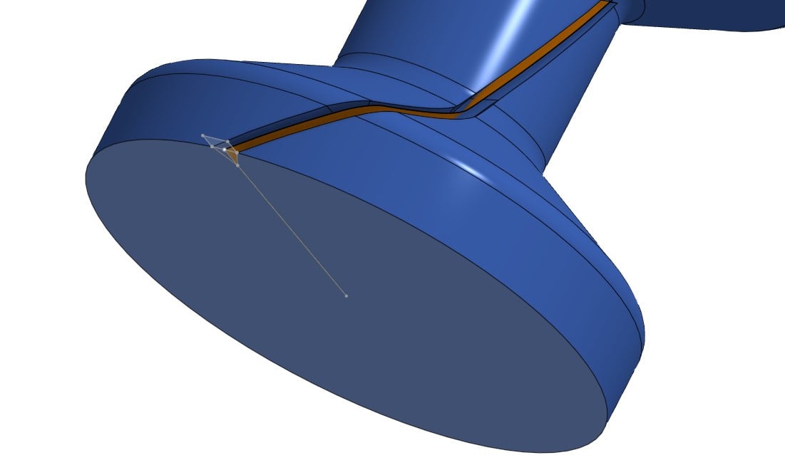
I can usually figure this stuff out but this one has me stumped. I have a revolved body (a spindle of sorts) and I'm trying to cut a V-notch the length of the spindle, while that notch rotates 3/4 away around the body. I've tried several ways, but none of the ways seem to get me what I need. I've looked around the forums and found tricks on intersecting curves, creating surfaces first to guide, etc etc, but none accomplish what I'm looking for. I need the sweep profile (the triangle cutting the notch) to keep the bottom of the notch always pointed towards the center/axis of the revolved body. I also need the profile itself (the triangle) to stay normal to the base/cross section of the revolved body. I can't seem to make both of those things true at the same time. Can anyone help me understand how I'd accomplish this? The fact the whole thing rotates around the face seems to be the complicating factor here.
Image of what I'm working with currently.
Answers
In this example you went only 1/4 away around. If you'd want to go 3/4 do you see how the notch would become extremely shallow?
Presuming you'd want some kind of cam follower in that notch, it's not going to work out well I expect.
The reason is this is relevant is that if you solve this challenge, you might still have to figure out a different way.
One perhaps more realistic way would be to design the cam follower, pattern it along the curve (with the right direction, that's still the challenge) and remove it. then create an approximate b-spline surface through those faces. this is a virtual milling approach…
My attempt: It's a challenge indeed.
I've given it a few attempts. this is how far I got with a bit of a complicated way.
The challenge with reapplied sketches like this one is that a tangent direction, or in this case the edge direction of the intersect curve, can flip and the sketch doesn't solve as intended like in this example.
If you really only need 1/4 of the way around iso 3/4, thing may be easier (less chances of a flip of direction).
Moreover I couldn't get the Loft to work with a query variable, so that will mean a lot of manual clicking.
with the #nr_steps the resolution can be increased once you get it to work well, but I doupt this is what you want to end up with so I'm quiting for today.
I've looked at ruled surfaces, but none keep the orientation of the 'triangle' flat.
So I came up with this complicated solution:
anybody with a simpler idea?
at least you can see how narrow the slot will be in height, so I'm not sure you'll be able to get it to work this way…
Am I missing something or isn't that achieved with the "Lock to profile faces" on the sweep?
https://cad.onshape.com/documents/e82e3042f8e8bfa8fe82f924/w/b38fe123c0c37de378e9691d/e/10f5abd0b3ffe016458aaed1
I should keep this old thread tabbed for this kind of discussion. Classic cam follower problem that needs Body Sweep capabilities to execute correctly but can be approximated by some ruled surface work and thicken magic. Profile sweeping alone is insufficient to capturing the true mechanics of a cam slot follower and maintain both the orientation and cross section of your sweep. Other people have made attempts with a wrap feature but this method fails on geometry such as yours. My example is for a simple cylindrical follower but you can add a chamfer feature to the sweep body to get your pin profile to match.
Derek Van Allen | Engineering Consultant | MeddlerI just had a thought…I'm wondering if I can change the profile to a circle first (even if small, such that it would be entirely inside the V-notch) first, since a circle would have no consequence to whether it stays pivoting around the body axis, and then make composite curves of either ridge that it cuts (either edge of the "canyon" and then loft those two lines together into a surface. That surface would then be, I believe, perpendicular to the line from the surface of the body and the axis of the body. Then I could hold the top surface of the triangle to that face.
That may not even work, but I'm hoping there is a more professional way to do this that isn't quite so convoluted. But as always, open to learning and best practices!
On the full spindle, the curve (which was projected via a helix) goes 3/4 of the way around. this was just a snippet that shows the rough variation of radius of the body that I'm dealing with and is zoomed in enough to show the relative profile size and the curve I'm trying to sweep it along. It wasn't meant to be a complete view, so sorry for the confusion there.
It's actually not a cam follower, it's much more simple. This is a spindle that will roll in the finished component which will be 3D printed. The goal of the notch is to provide relief for the Z-seam from printing. if the notch gets too shallow I'll have to deepen it which could weakin it or make it too deep elsewhere; and if I use a profile other than a triangle the missing flat can become too large. The reason it's rotated around the spindle is to avoid having a dead "flat spot" where the seams all align. By wrapping it 3/4 of the way around I can effectively make this perfectly round for the purposes of printing, eliminating any negative effect of the Z-seam on its ability to roll smoothly.
Eric, if you look at the cross section of your document, you'll see that the profile gets pretty severely screwed. the profile doesn't stay clean, it gets warped.
While this would get me close enough, a cam follower is a slightly different operation. I need the profile path to stay normal to the end of the revolved body (so original orientation), vs. a normal cam follower would have the cut profile stay normal to the sweep path.
Since this is for 3D printing, I'm looking for any single layer (cross section) of the profile to be identical, regardless of the relative angle of the channel in relation to the entire part. I need (want) a pocket that is just large enough to hide my seam, and by making the cut path normal to the sweep path, I'm making the gap at the surface of the part unnecessarily large. Granted for all practical purposes and the fact FDM is inherently imperfect it probably doesn't matter much but for the sake of learning and different methods for different operations I just wanted to point out that this is technically a different operation/solution I'm looking for.
@eric_pesty the lock to profile faces, as well as ruled surface solution that specify an angle to the surface, both find a normal to the face (to measure the angle from that's not aligned with the top face as Tracey was looking for.
@Tracey: now why are you looking to hide the seam in this particular way? and do you want to go 1/4 or 3/4 way around?
HI Tracey,
glad to hear from @Derek_Van_Allen_BD that it's actually a difficult modeling challenge and I was struggling for a reason.
indeed Somethings are easy in CAM software or slicers, but difficult to model.
This is true for supports, as well as seams etc.
I did a tiny 0.3mm diameter circle sweep accross the face to work as a 'seam attractor' and it works very well except for the steepest helical curve where the circle may need to be increased a bit (or the angle decreased).
Prusaslicer automatically put the seam in the corner:
They also rock a seam painter which could come in handy in this case.
more over, how about placing the seam position random? you'll end up with a closer to perfect cylinder that way. combine that with 'scarf joints' and you're good to go without any CAD effort…
Hi, and thanks for all the responses! Sorry for delays, my account I guess is still being moderated so there is a significant delay in when I reply and when it posts. Also my screen name updated I guess. :)
The reason I can't just do it in the slicer is Z seams create a little bump. While normally this doesn't matter, in this case, it does. For full context, this spindle/body in question is a roller for a roller bearing. I'm just an EDU user (husband and I are homeschooling our daughters, and our 9yo autistic daughter has taken a keen interest in CAD/3D Printing. My husband has more CAD experience, but still not professional level, but we can usually get it figured out. So we're just trying to solve little household problems with CAD and teach our daughter along the way. The need for a 608 Bearing for a filament respooler came up, and my husband thought we could have a novel way of just making one after not being happy with other models published if we can overcome the biggest issue in printing bearings, which is the z seam introducing grittiness or simply preventing the bearing from working at all. Given it's a light task (holding a spool) a 3D printed bearing could suffice for the need and pose a unique problem that teaches creative problem-solving. By hiding the Z seam in a crevice while simultaneously revolving it (the 3/4 turn is arbitrary, however 1/4 turn is not enough), you allow the seam to not cause a bump and by rotating the seam placement around the roller's axis, you eliminate any dead spot in the roller as well and give each of the contact surfaces a strong support. The 608 bearing is very small, only 7mm thick, 8mm ID, 22mm OD, so it's a challenge that may or may not pan out.
We cut a circle profile instead of a triangle (we've used this trick before, but never for a small bearing like this) and it worked remarkably well actually. The part printed well, and is very smooth, so now we're going to play and learn about tolerances.
https://cad.onshape.com/documents/e76c782e27a91938ec741e69/w/988e92e62660bb858034da39/e/85441efdc12a7e275cbc4181
For those curious, here is the model. Please forgive the crude CAD skills and mess…there are a lot of trial and error in this document and we're still learning OnShape as my husband is most familiar with SolidWorks (again, not a pro regardless), but the 3DExperience platform headaches and lack of being able to hop on any computer to model is what drove us to checking out the EDU license for OnShape over continuing with our SolidWorks Maker license for teaching our kids as we can use their homeschooling computer to run it in browser vs. needing a proper workstation.
As an aside, I found it odd that you cannot select an intersection curve or composite curve as a sweep path, but rather need to select every entity that makes up that curve separately. Not sure if I'm doing it wrong or if that's by design. Just seemed odd.