Welcome to the Onshape forum! Ask questions and join in the discussions about everything Onshape.
First time visiting? Here are some places to start:- Looking for a certain topic? Check out the categories filter or use Search (upper right).
- Need support? Ask a question to our Community Support category.
- Please submit support tickets for bugs but you can request improvements in the Product Feedback category.
- Be respectful, on topic and if you see a problem, Flag it.
If you would like to contact our Community Manager personally, feel free to send a private message or an email.
In 2026, What Is the Best Sketch Blocks Workaround in Onshape?
 Chris_Beckett
Member Posts: 27 ✭
Chris_Beckett
Member Posts: 27 ✭
I'm coming from SolidWorks and would like the same sketch blocks functionality in Onshape.
I've found a couple threads mentioning workarounds that are 3-5 years old.
Before I spend time trying them… what is actually the best workaround currently available in Onshape?
And is it on the roadmap to add sketch blocks functionality properly?
Previous thread found:
And this one:
Both were years ago. Any better methods now?
Best Answer
-
 eric_pesty
Member, pcbaevp Posts: 2,568 PRO
eric_pesty
Member, pcbaevp Posts: 2,568 PRO
Deriving a "surface" is a pretty decent workflow for this type of "bring in a shape you want to extrude" workflows, and once you get comfortable working with mate connectors (definitely something worth spending some time on as they are both a bit different and very useful in many places), it does give good control for positioning derived stuff.
For your other use-cases it looks like you are mainly talking about 2D drawings. Onshape's drawing sketching is still pretty limited, and doesn't let you "derive" things.For a title-block logo, it might just be easier to use an image… Or you include that in a layout sketch of your title block (done in a part studio) that you dump in your drawing template as a DXF. Here's what that looks like for me (note the 3rd angle diagram in yellow that could be a logo):
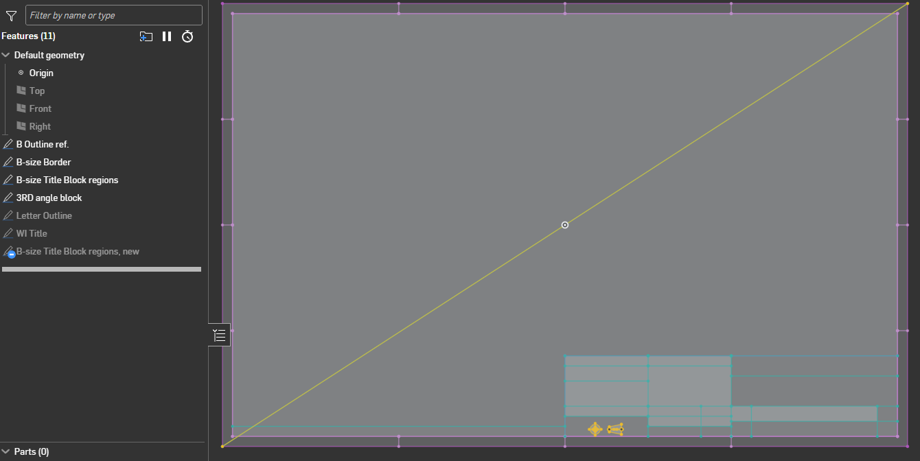
I throw in a diagonal line in the sketch that locates things nicely in the drawing template (bottom left at zero, zero) and delete it after importing in the drawing.
For use-case 3, the Autocad import can just be in a sketch that you insert as a view in your drawing, you can scale and move it around just like any other drawing view so I would think this should work reasonably well.
For use-case2, I think it would be the same thing where you would just insert a "view" of your 2D representation into any drawing you need it, but it won't work well if you need to "connect" other other sketch elements together in your drawing.
Basically you won't be able to do much "2D" stuff directly in drawings in Onshape so you have to work with 2D elements in part studios and/or assemblies and just insert these "blocks" as views in your drawing.
1
Answers
It would help to understand what you are trying to do as there might be different workarounds depending on the application…
For logos, my preferred workflow is to create "zero offset" surface(s) and create a closed composite of that. I typically include a configuration variable to scale it to the desired size. Then you can derive it in at the desired size and extrude or whatever the faces of the composite. If the logo has a lot of separate elements, using a query variable might be worth it to use for an extrude. (and the "Query variable +" FS allows importing query variables so I would definitely do that going forward!)
If you are looking for moving things around at the conceptual level, you can create assemblies of sketches and use mates on these.
Here's an example:
Here are three examples how I've seen sketch blocks used.
Use Case #1: Logos
Just a 2D representation of a logo. Saved in our Design Library. Bring it into a drawing. Scale it up or down and reposition it to fit a title block. Or into a sketch on a part to make a cut or extrusion in the shape of that logo. You can position it and scale it as required. Without any other constraints. (The nature of being a block constrains it).
Use Case #2: Electrical Components
2D drawing of things like resistors. We sketch things like how to attach a resistor to a pcb, then reuse that same resistor sketch on all similar drawings. The sketch is in our library. Just grab it and go. It's almost instantaneous.
Use Case #3: Electrical Circuit Schematics
I sketched a circuit diagram in AutoCAD because it's more free form and very easy to copy, paste, and move things all around. Import that into a dummy drawing in SolidWorks. Copy the schematic from that drawing into my actual production drawing. Select all the circuit elements. Click "Make Block." Now I can drag and scale that schematic block anywhere on the drawing. This has been super helpful.
These are just a few but the principle applies to many other things. For example in SolidWorks there's a library of all common steel extrusion profiles. Just grab one, put it into your sketch and extrude. Couldn't be easier.
For the last issue, the Frame features and optionally custom frame profiles work beautifully.
Simon Gatrall | Product Development, Engineering, Design, Onshape | Ex- IDEO, PCH, Unagi, Carbon | LinkedIn
That's a great feature for weldments. Thanks for introducing me to weldments in Onshape (aka "Frames").
Although that is similar functionality to a sketch block, it's not the real use cases I'm actually dealing with. I just mentioned that as a similar example.
So for this particular thread, let's ignore that one. Though it does show that similar functionality is possible in Onshape!
Will keep trying things for my 3 main use cases.
Deriving a "surface" is a pretty decent workflow for this type of "bring in a shape you want to extrude" workflows, and once you get comfortable working with mate connectors (definitely something worth spending some time on as they are both a bit different and very useful in many places), it does give good control for positioning derived stuff.
For your other use-cases it looks like you are mainly talking about 2D drawings. Onshape's drawing sketching is still pretty limited, and doesn't let you "derive" things.
For a title-block logo, it might just be easier to use an image… Or you include that in a layout sketch of your title block (done in a part studio) that you dump in your drawing template as a DXF. Here's what that looks like for me (note the 3rd angle diagram in yellow that could be a logo):
I throw in a diagonal line in the sketch that locates things nicely in the drawing template (bottom left at zero, zero) and delete it after importing in the drawing.
For use-case 3, the Autocad import can just be in a sketch that you insert as a view in your drawing, you can scale and move it around just like any other drawing view so I would think this should work reasonably well.
For use-case2, I think it would be the same thing where you would just insert a "view" of your 2D representation into any drawing you need it, but it won't work well if you need to "connect" other other sketch elements together in your drawing.
Basically you won't be able to do much "2D" stuff directly in drawings in Onshape so you have to work with 2D elements in part studios and/or assemblies and just insert these "blocks" as views in your drawing.
…just gimme sketch blocks!😂
I dunno, the lack of sketch blocks has been one more reason in a list of many that I've begun to untether myself from my sketchly constraints and embrace sketchless workflows. The stability of workflows that involve solids and surfaces is unmatched and sketches show up in fewer and fewer places in my work as time goes on.
Derek Van Allen | Engineering Consultant | MeddlerOne example where sketch blocks is needed for our workflows at Trek:
Our main silhouette sketch is a large sketch with many entities. Its job is to outline the major tube sections that make the side profile of a bicycle frame. It drives and controls everything downstream. It references our centerline geometry and other hard points. Water bottle clearance is something we need to design for. So having a sketch block of the silhouette of the bottle as sketch block keeps the main silhouette sketch more organized and prevents us from having to recreate it with each new project. The model is configured per size and needs the silhouette of the bottle to position main tube sections in that silhouette sketch. To do this right now requires us to add new sketch entities which can make that sketch hard to understand and manage. Using a sketch block would make this process so much better.
This is just one. Using solids and surfaces is a viable workaround when outside the sketch environment. Inside the sketch environment is where this capability is missing. @Vajrang_Parvate
I agree with you Derek, the more I use Onshape the less sketching I do. Bridging curve is one feature that has really has declined my sketch usage since transitioning from SolidWorks. Features are more robust as they have fewer references to lose - thinking about a converted edge in a sketch, it has 3 references, the segment and its 2 end points. Projecting the edge to a plane for sketch referencing is far more robust.
Finally! Someone who gets it. 🤣
PS if anyone else wants sketch blocks in Onshape please upvote here:
https://forum.onshape.com/discussion/comment/126010#Comment_126010
✋ I'd also like sketch blocks please…
But there are certainly pretty good workarounds for a lot of these cases using derives of sketches that live somewhere else.
The Onsherpa | Reach peak Onshape productivity
www.theonsherpa.com
Thank you Eric!
Your idea to put the DXF into a sketch in part studio and then locate that sketch on the drawing was the solution.
Much more complicated than it needs to be, since you can't really scale it or manipulate it within the drawing itself, but I was able to get the job done by using transform to scale it up or down in the sketch in part studio, then checking the drawing, then adjusting it again, etc.
You're right - the 2D sketching and manipulating is pretty limited in Onshape drawings. It's much more fluid and user friendly in SolidWorks currently.
I was surprised to see you had a whole drawing title block in your sketch in a part studio. But now I see why.
Thanks for all your insight and everybody else's. Much appreciated.
Don't forget you can dimension entire DXFs in a sketch with a single dimension - so you don't need to guess-and-check to get the size right.
Import your DXF to a sketch.
Use whatever construction lines or other helper geometry you need - but don't add a dimension.
As soon as you add your first dimension - it scales all of the imported sketch entities - keeping the aspect ratio intact.
(this is actually the base behaviour for sketcher - as soon as you add a dimension to any sketch, you can use that dimension to scale the entire sketch. As soon as you add a second dimension - now you have to change each dimension - or use the Transform tool downstream on a surface or curve or something).
Thank you @romeograham !
I was going to add that you could use a config variable to adjust the scale directly from within the drawing, however I found a bug (confirmed by support) where the auto-scaling doesn't work when the single dimension is set to a variable (config or otherwise)…
Sketch blocks would be a huge help for me now that I am working with lots of reused or iterations of shapes (tire tread lugs) or want to be able to use more than one dimension in a sketch as @romeograham has mentioned. It would be nice to be able to create sketch block libraries much like the frame profiles dialog. I also could see it as a group sketch entities option so that you don't have to dimension every entity to prevent the shape from changing, but then you could more easily scale and drag it around rather than using the transform tool.
100% would like it to work like frames profiles with the reference points.
Simon Gatrall | Product Development, Engineering, Design, Onshape | Ex- IDEO, PCH, Unagi, Carbon | LinkedIn
If I plan to move sketched geometry around, I usually sketch on mate connectors. These can then be used as reference points to align or otherwise manipulate these sketched 'blocks', even in 3D, which traditional sketch blocks would not allow.
There is one thing, though, that I miss: The ability to use the built-in OS transform tool on the MC. The lack of this limits the possibilities to editing the mate connector's coordinates manually, without any of the useful helpers like 'translate by line' or ' any method referencing existing geometry, let alone constraints. If we had this, I'd be completely fine without sketch blocks.
There are a lot of interesting workflows here I'd like to learn.
In your logo's workflow: How exactly do you create a "zero offset" surface? (I tried a couple of things but could only get it done with a Fill surface, which I suspect is mathematically more complex, isn't it?)
What's the advantge of deriving that instead of a sketch to extrude afterwards?
Thanks for your help
Any closed sketch region is a "face" in Onshape so you can just use the "offset surface" (with the offset set to 0)
Deriving this allows easier manipulation using the transform feature (which doesn't support sketches).
So it turns out you sort of can use the opTransform functions in Onshape's featurescript to do sketch manipulation but it comes at the cost of stability for complex regions and doesn't support decals. It's probably why they don't have a sketch bodies input in the default transform feature. I was able to vibe code a buggy feature in 5 minutes to prove the concept but it has regions which become invalid for the later extrude operation in the tree.
Here's the doc if anyone cares to get invested in making it a better feature than my non-attempt. Personally I'm sticking to resolving my geometry as surfaces before doing other stuff with them because it's more stable.
Derek Van Allen | Engineering Consultant | MeddlerI've also used the "transform pattern" FS to relocate derived sketches as it does support that (but not scaling) so I find the surface workflow to be more flexible…
Sketches are equivalent to faces in Onshape. You can use the Offset Surface feature with 0 as the input value and create a surface from the sketch. In fact, if you select the sketch from the feature tree while doing that, Onshape will detect all of the closed loops and automatically select the faces for you.
The advantage of the Derived workflow is that you can position and scale your geometry to your liking. The transform/scale tool exists inside of sketches, but it's not parametric and pretty difficult to control, so when you use Derive imported geometry (like surfaces or solids), you can place them where you like and scale them accordingly with the Transform feature (and its derivatives).
On the other hand, if you Derive a sketch and then extrude it, that might get the job done. But then if you have to keep deriving that same sketch and extruding it, you're just doing excess work, whereas you could do it once in your source part studio.
Ramon Yip | glassboard.com
@eric_pesty "(and the "Query variable +" FS allows importing query variables so I would definitely do that going forward!)"
What's the benefit to chose either "Load From Derived" (where the QV+ must exist in the seed file) or "Created by" (where it must not) in the case of logos?
Thanks. I get why using a Composite of surfaces is better now. That, plus configured width (and eventually Transform pattern FS) is a great workflow.
IMHO, allowing Extrude or Thicken with 0 (along the now possible Offset 0) is better.
I could configure also their values and have the choice of surface or solid, with the exact protruding height or emboss depth. All during Derived
QV+ saving and loading queries is intended for subsets of geometry selections to be picked up after the derive operation. My examples are all for 3d parts where you might want to do some faces as painted finishes on your unioned bodies and some faces as unpainted, or for sheet metal workflows where you convert a derived solid and have preselected exclusion faces or bend edges. That relates a little more loosely to a logo context but the paint colors via featurescript example is still relevant and you want to color different parts of the derive different things.
Derek Van Allen | Engineering Consultant | Meddler