Welcome to the Onshape forum! Ask questions and join in the discussions about everything Onshape.
First time visiting? Here are some places to start:- Looking for a certain topic? Check out the categories filter or use Search (upper right).
- Need support? Ask a question to our Community Support category.
- Please submit support tickets for bugs but you can request improvements in the Product Feedback category.
- Be respectful, on topic and if you see a problem, Flag it.
If you would like to contact our Community Manager personally, feel free to send a private message or an email.
Having the legend "question" above the box where you want a title is .... not good.
 buk_browseruk
Member Posts: 14 ✭
buk_browseruk
Member Posts: 14 ✭
How do I construct a plane at 45° to the axis of a cylinder?
I managed to create a radial plane half way up the cylinder, but cannot find a means to tilt it to 45°.
0
Answers
Sketch a construction line perpendicular through the cylinder axis, then use the "line angle" option when creating your plane
I created an example document on the Android phone app but couldn't figure out how to share the link from the mobile app.
Or just use a mate connector do it in one step…
Mate connectors....something I probably should learn more about. All I've used them for is to position parts of an assembly.
Thanks Eric!
@jim_zamecnik
"Sketch a construction line perpendicular through the cylinder axis,"
How?
How can I draw a line to put the plane on, when I need to plane to create the sketch so I can draw a line?
@eric_pesty
What would I be "mating" or "connecting" this plane to?
I only want this plane so I can create a sketch on it.
I can't belive how stupidly difficult is is to do this.
Nearly to hours of sessions with chatgpt and google's AI whilst waiting for my disappeared posts here to reappear, and nothing.
Dozens of attempts to simple tilt a plane to 45°.
In my current CAD, click "Move", Click the plane, click the direction handle. Type 45°. Done
The cleanest method is to use "Select mate connector" inside the sketch dialog. Then click any mate connector reference in 3D.
Then click to edit on this smaller mate connector symbol.
Which brings up the mate connector manipulator dialog where the mate connector can be moved and rotated around any axis, note that the axis is the local axis of the mate connector itself, not the global coordinate system.
The XY-plane of the resulting mate connector becomes the sketch plane and you can sketch away as you wish normally.
Here's the doc.
All of this and more is explained in the video linked by @eric_pesty above, great watch!
Sketch your line on your current sketch. Then use that line to create a "line angle plane" at 45⁰. Then you can create a new sketch on that plane.
https://cad.onshape.com/documents/7c165154098b00437acacab4/w/ed5856ae5b9212f36c3390ec/e/31de001658cb7daf32ebb751?renderMode=0&uiState=69fc9d1767af19aa08180a2a
That might get you to my document.
I still don't always get the link sharing right....
@wille_j
"The cleanest method is to use "Select mate connector" inside the sketch dialog."
3days wait for TPTB to authorise my response to a response to my question that took 3 days to authorise; and then only to have to question the very first sentence of an elaborate response. (Thankyou BTW!)
What sketch dialog?
I am sitting, not in a sketch, (is that what you call 3D), looking at my cylinder. I have exactly 2 (non-default) things in my features tree. A sketch on which I drew a circle, and the extruce to a cylinder.
I want (need) to construct an ellipse on a plane at 45° through the centre (axially and radially) of the cylinder. That ellipse will define the "cutting path" for a groove on a barrel cam.
So, is "the sketch" that original sketch? (Wouldn't modifying that screw up the extrade?)
Or do I need to create an new sketch (where) in order to gain access to this mysteriously named "mate connector", in order to define a plane in order to create the sketch I need to construct my ellipse?
@buk_browseruk Man, that is so basic, you really need to read the manual.
There is a "plane angle" option in the plane tool, and there are curve types called "construction curves" that won't 'screw up' your extrude. Now, after you used that, you only need to:
A - Use the split tool with the angled plane on your cylinder surface to 'cut' it, or
B- Use the tilt plane as another sketch plane and apply the "intersect" feature with the cylinder sleeve surface to create the ellipse as a 3D curve.
Or, if that fails, you could just
C- Sketch up that line at 45° and project it rihght on the cylinder to get the 3D ellipse.
Whatever serves you best.
But please take the time to go through at least the basic lessons in the leraning section. They are really good and will save you a lot of time and geusswork.
Hm.
The trouble is, there does not seem to be a"manual", just a plethora of long winded, slow video courses I have to sign in and wade through half a dozen to discover the one thing I want now;and then wade through half a dozen more to try and find the next thing.
Oh for a searchable and indexed manual.
I'm not a newbie to CAD, just a newbie to this CAD.
I thought I was missing something obvious that meant I needed to a) create a plane; b) draw a line; c) create a second plane that referenced that otherwise unneeded line that I now cannot delete else the dependent plane goes away.
Even FreeCAD — surely the worst CAD interface ever; least that's what I thought — allows me to create a Datum plan positioned according to some existing model feature and the rotate, and or translate it to where I need it as a simple, simgle operation.
willy_j's method of abusing a connetor to proved missing fucntionality seems cleanest — no unwanted auxilliary sketch and unneeded line cluttering the feature tree.
The mate connector route is meant precisely for this kind of use case. :P Plus, I place practically all my sketches on implicit mate connectors so that I don't have to maintain a separate feature or set of features constructing intermediate geometry. Makes navigating a complex Part Studio a whole lot easier.
The mate connector option is definitely the best option and what I suggested… The name isa bit mis-leading as it's used for a lot more than assembly mates. It's actually a coordinate system that can be defined on the fly.
Have you looked at the help files? It's definitely indexed and searchable.
There is also the "AI advisor", although it's very disappointing that it didn't suggest using a mate connector with the following prompts @_anton , who's in charge of collecting feedback on the advisor as this seems like a massive fail!
Also, it seems to be hallucinating things that don't exist in Onshape, "New Sketch on Plane" function, really????
And the absolute worst; I followed up with this and the answer made me want to scream:
I was literally just asking about ways to angle sketches and they didn't get mentioned so it's a good thing I'm told that's not the only thing they are good for! I really hate how absolutely dumb AI can be sometimes (often)!
/rant
Why's it called "mate connector"?
I wanted to reorient a plane; the first term that came to mind was 'move', followed by 'transform', followed by 'rotate' and 'tilt' and…I would never have thought to even consider something labelled 'mate' or 'connector' for this purpose..
Its like putting steering wheel of your car in the glove box and lablelling it 'directional widget'. (Actually, that's less obsure.)
There's a principle software design called the 'principle of least surprise'; this is more ;Principle of upsell the training courses.
Mate connectors were originally just for mating parts in assemblies. Over time, their use has expanded to anything that needs a plane or coordinate system. Since they have powerful functionality for locating and positioning, that's being leveraged and reused for other purposes.
Is it obvious terminology? No.
If you go through the learning pathways, you will learn about a lot of different ways to use them.
Simon Gatrall | Product Development, Engineering, Design, Onshape | Ex- IDEO, PCH, Unagi, Carbon | LinkedIn
Mate is a British/Australian figure of speach indicating a friendly relationship, like between a sketch and an angled plane.
I didn't know of the usefulness of mate connectors until recently. It's a feature that could use a better name. I propose "Really useful gizmo". I found the video Eric posted above pretty helpful, if you have 20 minutes to watch it.
@S1mon "If you go through the learning pathways, you will learn about a lot of different ways to use them."
That's exactly the problem with "learning pathways". I want to find a specific (preferably single, simple) solution to my immediate problem; not take a long and winding road, 95% of which is totally unrelated to my current requirement and which may or may not include an oblique (often unrecognisible) reference to the solution I seek.
It like asking "How do I get to the hospital?" and being told to take the walking tour as it will (evenually) pass by it, though it might not be pointed out specifically.
@jim_zamecnik "I found the video Eric posted above pretty helpful, if you have 20 minutes to watch it."
I did watch the entire thing, and if how to apply a mate connector to a plane is in there, I didn't see it. The only starting point (for a mate connector) seems to be the button on a sketch, which means I need a sketch, which means I need a plane to construct the sketch on which…brings us full circle.
@eric_pesty "Have you looked at the help files? It's definitely indexed and searchable."
Where? When I click on the "Help menu" dropdown I see:
Nothing there is obviously a manual, and nothing I clicked on in there looked like one either.
Click on the "help" item and I get a search box. Ask my question there and I get:
Same for 3 other variations I will not bore you with.
12 days on from my original enquiry, and due to the 3 day turnround between posting and approval, I'm no nearer to solving my original problem: that of how to find quick answers to ostensibly simple questions.
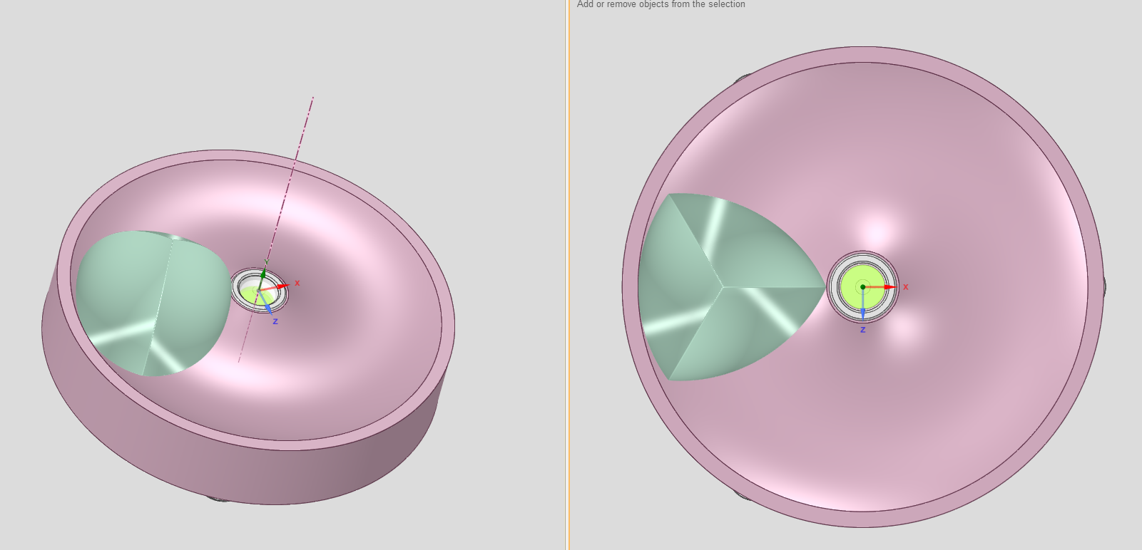
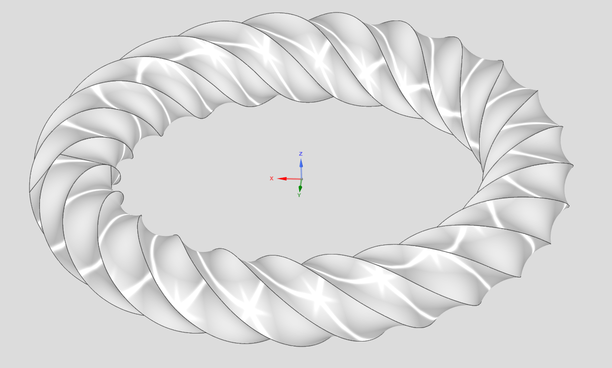
This is what I was trying to draw:
Took me about 10 minutes in my CAD; but I was doing it for a friend who wants to use it in OnShape, so I tried here. 12 days later…
We settled on FreeCAD — which I dislike with a vengence — but at least the help is easy to find. It took about an hour there.
I guess I now know why all the YT videos I see promoting this product either show a simple sequence of drawing a simple 2D shape and lofting it to a planer 3D object, or just a static image of "their design". Enough for sponsership, but nothing more complicated.
Being british, my mate wants me to go for a drink with him Sunday lunchtime, but my mate wants me to stay home and help her, and she's offering a mating reward. (Guess who won!)
But using that as a justifiction for the "mate" prefix to a (industry standard term) "connector"; and implying it is logical? Obvious? Derigour?
Not so much pal!
Sorry 'bout that mate!
(I tried! 😉)
@buk_browseruk ”I need a sketch, which means I need a plane to construct the sketch on”
This is not true. And exactly what I’m explaining in my previous comment. You start draw a sketch, instead of selecting a plane you create a mate connector directly in the sketch dialog, you don’t need a plane prior at all.
To take this even further, planes are actually superfluous in Onshape. Onshape is not like other CAD tools, it has been designed from the core to uproot and improve the old ways, and as such it takes a bit of patience in re-learning old habits. Instead of going searching for a button that you won’t find, search for the methods that take you further.
@buk_browseruk
There is a lot of back and forth here about mate connectors and angled planes to produce your sketch. You most certainly want to learn how those work since they will save a bunch of time for all work in OS.
In the mean time the 'WRAP" feature will will get you there much quicker for a slot like this.
Ps. Half wrap and mirror because OS has a problem if you go 360deg. Produces a non manifold condition or the like.
https://cad.onshape.com/documents/ec9994607320087db3682d12/w/187cdb6ffb9d97c20a33dacf/e/99e818eef3ebeb13e7411e50
@willy_j "This is not true. And exactly what I’m explaining in my previous comment. You start draw a sketch, instead of selecting a plane you
create a mate connector directly in the sketch dialog, you don’t need a plane prior at all. "
Well. I eventually got a sketch plane tilted at 45° to the centre of the cylinder, without an intermediate sketch or plane. And I even managed to start to construct an ellipse on that sketch plane at its mid point, but from there, with no method obvious to reference cylinder that defines ellipse I need, and no apparent way to orient it to the workspace ordinals; nor even orient the sketch plane to the screen whence I might eyeball the edges of the cylinder, nor any way to type in the mejor and minor diameters; the whole exercise to this point is useless.
"To take this even further, planes are actually superfluous in Onshape. Onshape is not like other CAD tools, it has been designed from the core
to uproot and improve the old ways, "
If I offered you a car that used a foootpedal to select gears, eye movement detection to control steering, and up and down buttons to control speed. No brakes, just hit and hold the down button until you stop. It takes a bit of patience in re-learning old habits, but it a much better system in the long run. Assuming you don't kill yourself first.
You up for it? You gonna trade your car for mine?
There's a reason cars all have the same or very, very similar controls…
Hm. Thanks for taking the time, and sharing the document. Trouble is, having spent nearly an hour looking at it, I have no idea how that works!
The idea is manually constructing the 2D projection of a 3D slot in a cylinder in order to wrap it onto that cylinder seems…politely, backwards.
Frankly, I have no idea how I would go about constructing that shape.
One last attempt to get some help with this. Here's how I do this is my CAD. (According to the gif recorder, this sequence took 2.15 minutes before compression!)
Could one of you kind gentlemen produce a similar gif/video of you doing this using OS?
Also, if there is a text based help system, could someone please point me at it? Cos I have not found it.
This is where the breakdown is happening. Design Spark is a direct modeling tool, whereas Onshape is a parametric-based program. Think of it more like Fusion 360 or SolidWorks vs Design Spark seems more like Rhino or Sketchup. If you've never used parametric CAD programs, then it would make sense that you're not used to it.
I have my obvious biases, but I'm not gonna tell you which one is better or worse. You just need to get over the initial growing pains of learning a new CAD tool.
That said, this is what I actually used to learn Onshape, coming from 10+ years of Inventor Fusion and SolidWorks combined. It's a K-12 learning set of written tutorials with GIFs.
https://learn.onshape.com/learning-paths/intro-to-cad
Ramon Yip | glassboard.com
@ry_gb "That said, this is what I actually used to learn Onshape, coming from 10+ years of Inventor Fusion and SolidWorks combined. It's a K-12 learning set of written tutorials with GIFs. "
I went and looked at that tutorial. Eventually found my way to a "carddeck"., clicked the first card and "the history of cad". ….. I want to learn OnShape, not take a history lesson. Click. Done with that.
I take it that as you are promoting that, there is no text manual with an index and a (non-dumb-AI) search facility.
20/30/40 hours of 20minute videos where the talking head/narrator spends 5 minutes telling what he's gioing to tell me, 5 more telling me what he isn't going to tell me in this video cos that in (one of the 19) a subsequent vid; 5 more minutes telling me what he just told me. And 5 minutes on actually telling me something pertinent, 50%+ of which is reiterating stuff from previous vids in order to get to a point where he can demonstrate a dozen variations of the use of one "new" feature; is no substitute for being able to look up how to use a particular feature; or perform one specific task.
"Onshape is a parametric-based program." And that seems to be code for "It's a serious CAD program, so it has to be difficult to use!"
I am also quite familiar with and quite competent with (despite my strong distaste for its horrible UI) FreeCAD. I'm also familiar with (have installed), Fusion, Blender, OpenSCAD, MoI and Plasticity.
I trained (a long time ago) as a draughtsman; and subsequently made a 40+ year career as a programmer specialising in 3D graphics engines and UI design. I'm not a neophyte anywhere but here.
What I attempted to do in this thread, starting with its title, is document the pain of a new user here.
I am fully aware that OS is "parametric", but I do not consider either a justification nor an excuse for total opacity of the new user experience here.
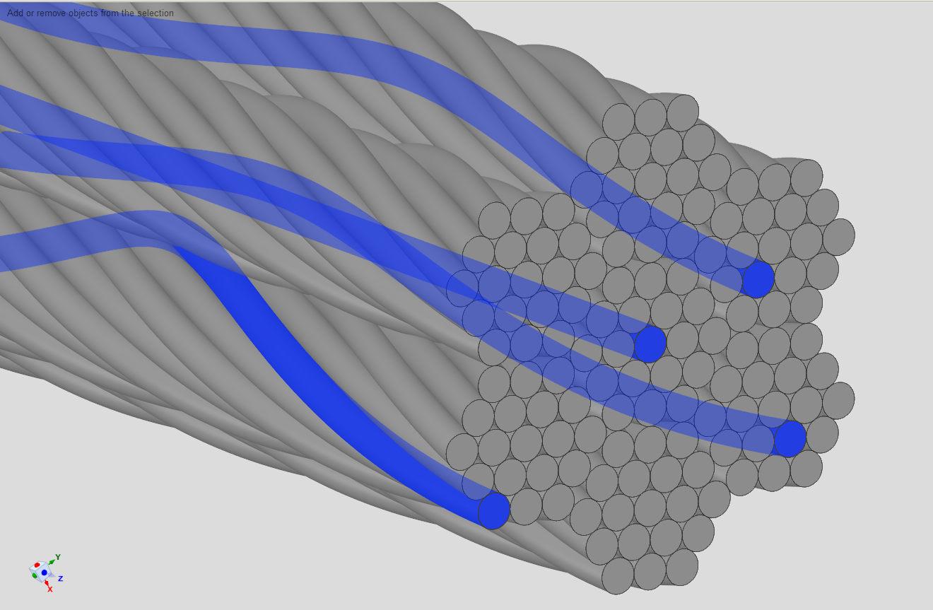
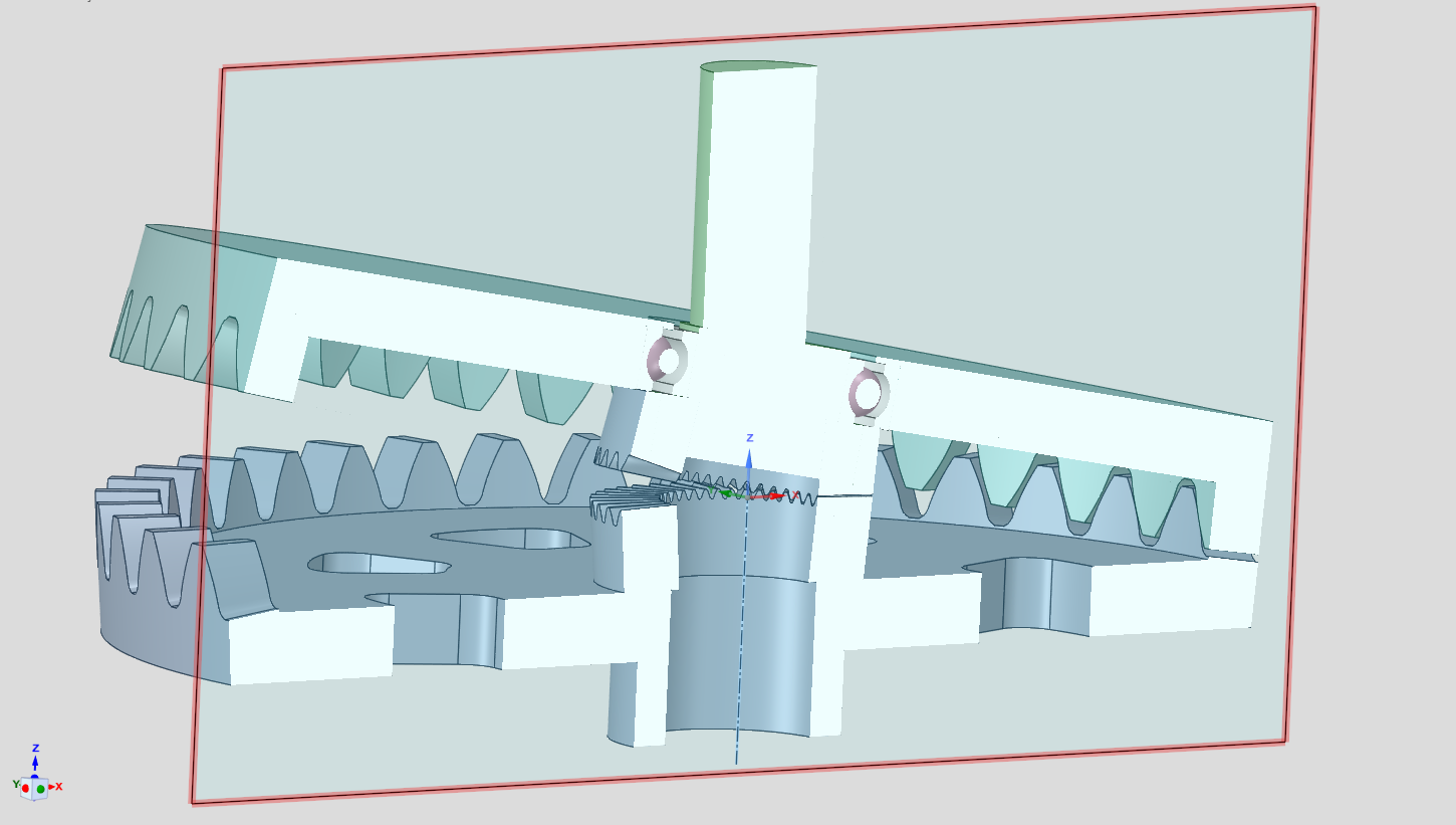
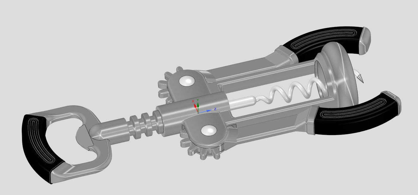
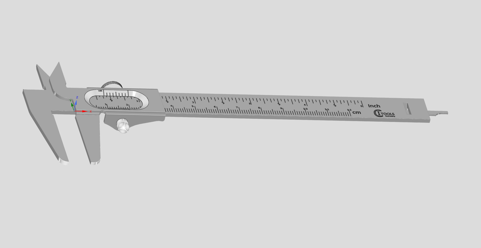
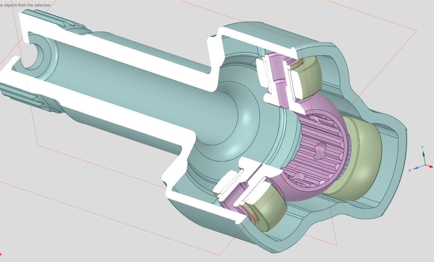
I guess this thread has pretty much run its course now. And I go back to using DSM. Not because it is perfect, because it certainly is not. I would not be looking to learn OS if it were. And not because I am too dumb to use "parametric CAD"; but simply because if it is this hard (over 2 weeks and counting) to work out/find out how to do something as trivial (2"30'!) as the above, then how hard would it be to work out how to construct models like these:
@buk_browseruk
No CAD system is perfect, and in each CAD, users develop workarounds.
If I am following your design intent, I think this method gets there.
https://cad.onshape.com/documents/a7d16049bf0952557f32b42f/w/05580a6f0e4926953456a2bd/e/565dc27390643495b62e8192?renderMode=0&uiState=6a0b3708524d70d07f2f620d
@buk_browseruk
I'm trying not to be too negative here (EDIT: I think I failed that part…) but I find it surprising that someone with your experience doesn't have the curiosity required to take an open minded approach to learning a new piece of software and its UI…
Onshape has been "stealing" users from other CAD systems (myself included, I was a long time Solidworks user before) and most don't seem to have a hard time picking it up. There are a few things you might consider "unconventional" that require slightly different workflows or techniques (like the mate connector), but my experience with Onshape has been that there is a solid reason behind the choices made (even if I don't agree with all of them) and it generally makes sense if you put in the time to understand it.
Regarding this specific discussion, creating an angled plane in Solidworks would require the exact same workflow of first creating an axis (either as an intersection of planes or a sketch line) to rotate the plane about so I really don't see why you weren't able to just do this if you have experience in Solidwork! Speaking of UI, Onshape's UI is much cleaner and streamlined, and definitely a lot more consistent than most of Solidworks'.
The mate connector in Onshape is just a faster way of achieving the same thing. I was disappointed that the "AI advisor" didn't suggest the mate connector option, but it did suggest a valid workflow (plane-angle) plane as it's second proposed solution, again, as a Solidowrks user, that should have been all you needed. Then you just have to use the "intersect" tool in the sketch to generate the ellipse on the sketch plane, again, pretty standard parametric CAD stuff...
That said, software in general, and especially parametric CAD, usually have more than one way to achieve something. In this case you don't even need to create a sketch at all as you can just use a split face to generate that, which is simpler and more robust.
You say it has taken two weeks to learn how to do something trivial that you can do in 2:15 in your "other CAD", but I would counter it takes 45s to do in Onshape (see attached GIF) using pretty basic parametric CAD tools (except maybe the mate connector, but it would only take a bit longer if I were to construct an angled plane and the extra sketch)…
One of the steps you appeared "stuck" on was saying you needed a plane to create a sketch. You are telling me as a UI design expert who has used a variety of 3D software, you didn't realize/think to try clicking the "sketch" button doesn't require pre-selecting anything? The "box" at the top of the sketch dialogue (with an "X" on the right of where it shows the name your current selection) is a selection box that behaves exactly the same as all the other features (eg an extrude). There are even tooltips displayed when mousing over the various elements.
The interface certainly isn't perfect and may not be to your liking, but it's definitely not "obscure"!
As far as "having to sit through hours of video" and not having a written "manual" (I have a feeling fewer and fewer people are interested in these), there is detailed help on exactly how every feature works. For example if you look for "plane" in the help, the first result literally takes you to a page that goes over every option in the plane dialogue. This includes two introductory videos, a 30s one going over over the basics of using an offset plane, and second 1 minute long video going over all the other options, including the line angle you needed. If you prefer to read, there are also sections with step by step instructions and pictures when you scroll down. The answer to your original question was literally a few clicks away in the help so it really doesn't look like you put much effort into figuring it out! By the way that same "Plane" entry is the second result when searching for "create a plane at angle". The help also has an indented structure on the left, if you don't want to use the search box you could navigate to Part Studios/Feature Tools/Plane
So when someone who claims to have as much experience as you do is complaining about how bad the software/UI/training is, citing they were unable to perform a certain simple task after two weeks of trying (including getting assistance in these forums), I'm afraid it tells more about yourself than the software…