Welcome to the Onshape forum! Ask questions and join in the discussions about everything Onshape.
First time visiting? Here are some places to start:- Looking for a certain topic? Check out the categories filter or use Search (upper right).
- Need support? Ask a question to our Community Support category.
- Please submit support tickets for bugs but you can request improvements in the Product Feedback category.
- Be respectful, on topic and if you see a problem, Flag it.
If you would like to contact our Community Manager personally, feel free to send a private message or an email.
Please help me understand why the dimensions on my drawing seem incorrect to me.

Here is a drawing I found online that I'm working with as a exercise.
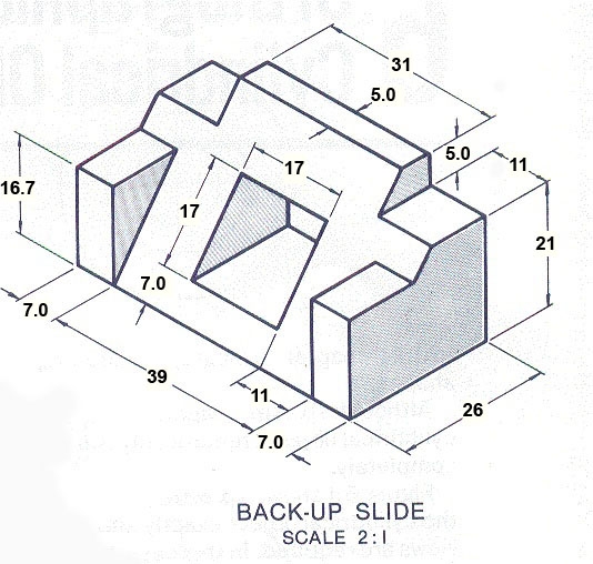
I can create the model with the correct dimension but I'm having trouble getting these three dimensions to display correctly on my drawing.


When I go to create the drawing this is the best OS seem to do.

How do I correctly display them three dimension on my drawing?
Edited to add:
I see how to manually add the dimension to show what ever I want, but shouldn't OS be able to automatically display these three dimensions like it does for the rest of the dimensions on my drawing?

Here is my model.
https://cad.onshape.com/documents/941b9c69311c0ca8e4886864/w/eab2e84dcc88f6a53636bf92/e/e3d7e0d8bc934967d0973f5d
Here is my drawing.
https://cad.onshape.com/documents/941b9c69311c0ca8e4886864/w/eab2e84dcc88f6a53636bf92/e/41b369c67afd6c09d2d284cd
Thanks!
I can create the model with the correct dimension but I'm having trouble getting these three dimensions to display correctly on my drawing.
When I go to create the drawing this is the best OS seem to do.
How do I correctly display them three dimension on my drawing?
Edited to add:
I see how to manually add the dimension to show what ever I want, but shouldn't OS be able to automatically display these three dimensions like it does for the rest of the dimensions on my drawing?
Here is my model.
https://cad.onshape.com/documents/941b9c69311c0ca8e4886864/w/eab2e84dcc88f6a53636bf92/e/e3d7e0d8bc934967d0973f5d
Here is my drawing.
https://cad.onshape.com/documents/941b9c69311c0ca8e4886864/w/eab2e84dcc88f6a53636bf92/e/41b369c67afd6c09d2d284cd
Thanks!
1
Comments
Ok, that makes sense. How would a professional go about showing these three dimensions on a drawing for this part?
Maybe the 17x17 as shown on the original image I'm trying to work with has the dimensions displayed incorrectly to start with?
Would a professional drawing normally even include dimensions on the isometric view?
Thanks,
Good to know, thanks!
True dimensions, good to know. This is just a hobby for me, but I really want to be as professional as I can about it.
I started out wanting to learn CAD for 3d printing. Started with SketchUp. After 30 days of working with SketchUp I purchased my first 3d printer.
Shortly after that I ended up coming across Fusion 360. From there I worked with Fusion 360 for about six months before I come across OnShape.
So that's been my limited experiance with CAD so far, but I have to say that I'm very impress with OnShape. I don't know if CAD can be a hobby itself as I started out thinking I was going to be getting into the 3d printable hobby craze and CAD would just be a tool I use for it, but I enjoy the CAD side of things probably 10x more then the printing part of it as of now. Maybe I need a better printer haha.
Thanks again for OnShape and keeping it free for guys like me.
Make a quick drawing to have something built, why not have them?
Are you kidding me?
DIMENSIONS ON ISO - It’s been used, maybe more than some realize
The world’s leading residential construction hardware company, Simpson Strong-Tie, has been using iso dimensions for decades. I remember their 3D drawings with dimensions being used back in the late 1970’s / early 1980’s
You used to walk into any lumberyard or construction hardware store, and there would be a stack of Simpson booklets with their easy to decipher illustrations
If you have the Home Depot app on your smart phone, in the search, type in a35
The A35, or as some of us old farts know it, the TECO clip, is one of the most widely used pieces of hardware there is.
I don’t think Home Depot or Simpson would mind me posting a diagram showing this example
When I was just getting into construction, an architect showed me Architectural Graphic Standards. A book with stunning drawings. This book also had a fair amount of dimensions on iso‘s. Dimensions on perspectives
Those that only deal with the learned engineering sort, maybe they don’t see much need.
Myself, I’ve long had the view that it isn’t all that bad an idea to illustrate in a way that conveys the subject matter as quickly as possible. An iso with dimensions can do that. This idea is especially nice if you have to deal with a set of plans that has a ton of details.
Evidently, Simpson long ago realized dimensioned ISO’s were going to help them better convey to the masses
Not hard for me to think those ISO’s helped make Simpson the industry leader that they are today
For any curious to see how Simpson Strong-Tie has been using 3D dimensioning for decades — download their Wood Construction Connectors Catalog, and thumb through it
Wood Construction Connectors Catalog | Simpson Strong-Tie
And for the record. I have absolutely no stock in or ties to Simpson. My only connection is being a person that has used a ton of their products
@alnis is my personal account. @alnis_ptc is my official PTC account.
No question in my mind that it can provide clarity at times that is not available with flat projections for the casual user. The response I've had from professional customers has always been positive.
I also would find it very useful to have the "true" measurements in the isometric view. It helps to quickly convey ideas when putting together requirements during product development stages. I have little to no use for projected values.
Vote and/or discuss this Improvement Request:
Simon Gatrall | Product Development, Engineering, Design, Onshape | Ex- IDEO, PCH, Unagi, Carbon | LinkedIn
I too would liked to add true dimensions to iso drawings.
Personally I think that until this is possible there is no point in allowing drawing of dimensions that are wrong and meaningless. It's just confusing and error prone especially to newbies like me