Welcome to the Onshape forum! Ask questions and join in the discussions about everything Onshape.
First time visiting? Here are some places to start:- Looking for a certain topic? Check out the categories filter or use Search (upper right).
- Need support? Ask a question to our Community Support category.
- Please submit support tickets for bugs but you can request improvements in the Product Feedback category.
- Be respectful, on topic and if you see a problem, Flag it.
If you would like to contact our Community Manager personally, feel free to send a private message or an email.
Help translating process flow from Solidworks to Onshape for FRC team
 derek_ward
Member Posts: 73 EDU
Hello, I've been dabbling with Onshape for the past couple of years now and I definitely see the potential, and I've used it very successfully for many projects at my school, but I've been having a hard time converting the workflow that my FIRST Robotics Team uses currently in Solidworks.
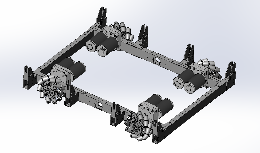
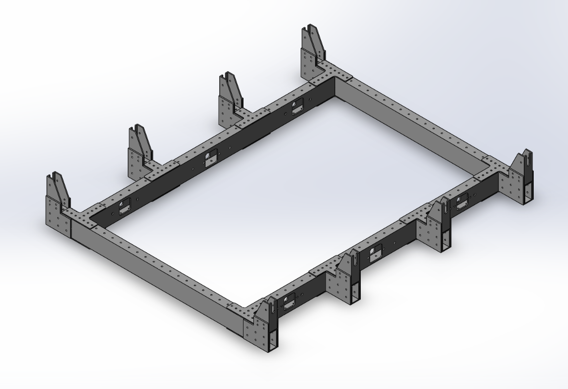
For example, to create our chassis we usually use a combination of aluminum 1" x 2" tubing, gussets, gearboxes and wheels from Vex Robotics. We typically make our chassis in the West Coast Drive orientation (it looks like a Roman Numeral 2). Below is a picture of our chassis


To make this we typically start with a layout sketch on paper and start to construct the individual 2x1 tubes and bring them into an assembly, mate them appropriatly, add gussets, bring in gearboxes and position them accordingly, edit the parts within the assembly, make the cuts and continue to build up the chassis assembly.
I'm having trouble converting that process to Onshape because of the different paradigm that Onshape has and the fact that we need to deal with third-party parts and assemblies. For example, I can easily create a chassis from tubing in Onshape, however, should I bring in the gussets via Derive into the Parts Studio, translate them to the proper position via mate connectors, or should it happen in an assembly? Perhaps I need to explore in context modeling further? Below is a link to our Solidworks model for the above chassis. Any advice would be greatly appreciated.
https://drive.google.com/drive/folders/1dh-LyxZRTGglD5rZHjf_tIFIOM1e9oQN?usp=sharing
Here's a link to an Onshape document where I'm trying to recreate the chassis.
Here's a link to an Onshape document where I'm trying to recreate the chassis.
Tagged:
0
Answers
1) In a part studio, create a layout sketch.
2) Create a dummy part (i.e. a block in the center)
3) Create mate connectors at key locations of your sketch (likely vertices at corners, etc.) with that dummy part as the "Owner part"
4) In other part studios, use the derive feature to bring that sketch and its mate connectors in.
5) Model new parts referencing that layout sketch (e.g. extrude from one end of a line to the vertex on the other side using the "up to vertex" end condition)
6) Insert new these new parts into the assembly and make use of your pre-defined mate connectors for easy mating
Here is a public document I whipped up to show how you can create such a layout sketch. https://cad.onshape.com/documents/7cf5926f1554396947c911ef/w/5d8e7ced7ddbdbeeb23619e3/e/3f9f49df5a5d6dcb26ab4888
Editing in context is a powerful workflow and has its uses. You could even use it to achieve a similar thing as above without the use of the derive feature. It is most useful if you are trying to design around an assembly's range of motion, or if you need more than just some lines in a layout sketch to create geometry (e.g. a complex interface between two parts). You can learn how to use it here: https://learn.onshape.com/courses/managed-in-context-design
Hopefully this gives you a good starting point!
-Noa
Thank you both so much for the suggestions! I'm going to try them out. Also, @mohir, I think you need the dummy part since MCs need to be attached to a part, no?
@derek_ward, right. I know the reason for the dummy part. I just don't think having the MCs attached to the part is necessary enough to require the dummy part. I would just add the MCs to the layout sketch at the assembly level - either ahead of time or on the fly while creating mates.
Twitter: @onshapetricks & @babart1977
If you would like to have mate connectors owned by sketches, there is an improvement request for it.
https://forum.onshape.com/discussion/8162/mate-connectors-in-sketches
IR for AS/NZS 1100
If you wanted to keep things simple, doing as @mahir and @brucebartlett suggest is a good idea.
OwS
HWM-Water Ltd
Twitter: @onshapetricks & @babart1977