Welcome to the Onshape forum! Ask questions and join in the discussions about everything Onshape.

First time visiting? Here are some places to start:
  1. Looking for a certain topic? Check out the categories filter or use Search (upper right).
  2. Need support? Ask a question to our Community Support category.
  3. Please submit support tickets for bugs but you can request improvements in the Product Feedback category.
  4. Be respectful, on topic and if you see a problem, Flag it.

If you would like to contact our Community Manager personally, feel free to send a private message or an email.

Transformable Boolean operation (Sweep with body as tool)

johannes_wjohannes_w Member Posts: 25 PRO
Recently I had to design a guiding slot. The function was to transform a horizontal rotation of a ring into a vertical angle change of a pin. The basic concept looked like this:


In CAM or real world milling, such geometries are no problem since you can define all axis of a tool and move it around as you please. But in the CAD design itself, it's a real pain. I managed to create the geometry by using several rotation cuts, a lofted surface which got thickened afterwards and finally a Boolean subtraction.

I've added the above example so you can understand the origin of my idea and my motivation. I started to program a custom feature which does a Boolean subtraction by moving a body in 3D space. With this feature, very complex surfaces could be created in a short amount of time without having to play around with curves, extrudes and subtractions. Simply put, a sweep which is able to use a 3d body. This is where I stand right now:


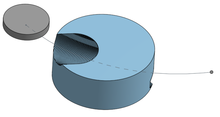
The procedure is to move the tool by certain increments along the curve and do a subtraction after every transform. It works better than expected but the resulting surfaces aren't usable since they are not tangential to each other.

@Jake_Rosenfeld and @NeilCooke already helped me with the transform along the curve. Now comes the tricky part, has anyone any idea/concept of how to smoothen the cut surface? I really appreciate any help and I hope I can create a stable and reliable feature in the end that's also useful to others. I've just got into featurescript.

Feature plans are to add the possibility of using several curves to define the orientation fo the tool. For example one curve that guides the tool by its origin and aligns the tool axis normal to the curve, and a second curve that defines the orientation of the tool.

Comments

  • MBartlett21MBartlett21 Member, OS Professional, Developers Posts: 2,034 EDU
    Could you show a link, please?
    mb - draftsman - also FS author: View FeatureScripts
    IR for AS/NZS 1100
  • NeilCookeNeilCooke Moderator, Onshape Employees Posts: 5,305
    edited December 2018
    Senior Director, Technical Services, EMEAI
  • konstantin_shiriazdanovkonstantin_shiriazdanov Member Posts: 1,221 ✭✭✭✭✭
    edited December 2018
    Its all about envelopes, the idea is flying in the air, but seems like there are no general and robust solution with appropriate perfomance.
    A few thoughts:
    - envelope for the myltyface body is significanly harder to generate then the envelope for a particular face or a limited set of faces of that body.
    - envelopes for cylinder faces may be made by sweeping cylinder axis along the path, and then creting offset of the resulting surface.
    - envelope for rotational faces of the bodies may be created by sweeping their cross section along the path.
    - envelopes for the outer sharp edges may be also created by sweeping those edges along the path.
    - for the general shape faces you may need to generate a number of intermidiate positions of the face geometry, and try to pick the points, for cross sections for lofted surface with some method - for example using the secting lines as in my Envelope FS.
    - for some general shape envelopes complex bodies should be decomposed into primitives so that you could use the rules from above for each of them separately.
  • MBartlett21MBartlett21 Member, OS Professional, Developers Posts: 2,034 EDU
    For extruding parts you could use this feature:
    https://cad.onshape.com/documents/4c823d07455a41d1f8da02fe

    mb - draftsman - also FS author: View FeatureScripts
    IR for AS/NZS 1100
  • johannes_wjohannes_w Member Posts: 25 PRO
    First of all, thank you for your participation!

    @konstantin_shiriazdanov yes I agree! I've experimented with creating a loft using the outer  edges of each section. This COULD result in a surface where all section edges are tangential.
    Regarding the sweep method, I guess it is very perfomance eating if I create with every section a new sweep which has to find the outer edges of the cut, create a profile and do a sweep to the next section. The problem is also, a sweep alows no deformation of the profile like a loft. So it could happen, that the sweep end does not have the same profile than the starting profile of the next sweep. So you have edges again.

    I've checked out your FS and it is very impressive! This already works very well! But in your case, you created different sititations of how to use certain tools. Like gears for example. I'd like to create a feature where any body can be moved along any path using any rotational movement. I hope I can manage that somehow one day. Let's see about that :)

    @mbartlett21 Yes you're right. Here is the link. Please excuse my somewhat primitive programming skills :)

    Regarding the other FS you've sent, it's not quite the feature I need. But thanks anyway!

  • MBartlett21MBartlett21 Member, OS Professional, Developers Posts: 2,034 EDU
    You should be able to sweep each face individually @johannes_w

    mb - draftsman - also FS author: View FeatureScripts
    IR for AS/NZS 1100
  • konstantin_shiriazdanovkonstantin_shiriazdanov Member Posts: 1,221 ✭✭✭✭✭
    when the envelope is made by sharp outer edges it can be easily made with sweep or loft like that:
    the probmes begin when you had to deal with envelopes made from some variable internal regions of the faces
  • johannes_wjohannes_w Member Posts: 25 PRO
    edited December 2018
    I did the EXACT same thing before I've read this post. And I came to the same conclusion.
    I have decided to limit the possibilities of this feature to cylindrical shapes. Like a milling cutter. This should cover nearly all CAM situations you may have when designing such geometries. Like in the first example I've posted.
    I thought about do a subtraction on the begin of the path, transform the body to the end of the body with all angle parameters and do another subtraction. Then I'd use the path and the envelope of the body to make a loft along the path. Sweep isn't possible since sweep doesn't allow me to change the angle along the path with a second guiding curve.
    There is one problem though. The end profile of the loft is not planar. If I may use the first example again:

    As you can see, if I created an end profile that's normal to the end tangent of the guiding curve, the loft would cut too far on the bottom.
    Also, the tangents from the cutting surface to the geometry of the body (yellow lines) isn't parallel to the axis of the tool which is normal to the viewing angle right now.
  • konstantin_shiriazdanovkonstantin_shiriazdanov Member Posts: 1,221 ✭✭✭✭✭
    edited December 2018
    so if you about rotational bodies, you can modify @mbartlett21 's Extrude body FS and try to change internal extrude of outline profile of the body to the sweep (or loft). the trick is to correctly make a plane for outline projection
  • johannes_wjohannes_w Member Posts: 25 PRO
    Yes I agree this FS has the same concept. Pattern a part to the sought location and connect the outline projections of the two parts. But as soon as there is a change of orientation, you can't use a plane for the outline projection. If this were the case, everything would be much easier and such a FS wouldn't be needed in the first place. Let me show you an example:
    In this case, a milling cutter rotates its axis vertically while performing the transform. On the starting point everything works out since the cutter starts horizontally. But when it comes to determining the end profile you can't use a plane to determine the outline projection. The inner side (right) would require a plane like the sketch I drew for the revolve. But the outer side (left) would require a plane that is normal to the tangent of the guiding curve.
  • konstantin_shiriazdanovkonstantin_shiriazdanov Member Posts: 1,221 ✭✭✭✭✭
    edited December 2018
    then what if you create a number of outlines for the parts in intermidiate positions and use them as profiles for loft?

  • johannes_wjohannes_w Member Posts: 25 PRO
    That would be possible. However, I think that creating single sections of the outline projection would really complicate the process and make the loft very complex.
    Right now I'm trying an approach of creating an extra surface that has that twist and use that surface for the end profile. It works but not 100% precise unfortunately.
  • romeograhamromeograham Member Posts: 656 PRO
    What I'd be interested in, is to be able to use the rotated end of the swept body to represent what happens when your toolpath doesn't go all the way through a part.

    A very simple example is correctly representing a blind chamfer:


    As you know, a chamfer + a fillet won't work, since the fillet can't be applied in the correct "orientation" to accurately represent the spinning mill in this case.

    I make a body (this is very simple because the edge I am using is straight) that represents the mill during motion AND at the end of the path, then do the Boolean to subtract:


    Could this FeatureScript you guys are talking about include the "end condition" that I'm talking about? 


  • romeograhamromeograham Member Posts: 656 PRO
    I did try your Extrude Part FS @MBartlett21 but it didn't work in this case:


    Could it be the vertex at the bottom of the part that makes it fail? (I did try it with a non-pointy bottom end and it still failed).


  • johannes_wjohannes_w Member Posts: 25 PRO
    Exactly @romeo_graham392. The end condition you are talking about is exactly what I'm trying to achieve.

    Unfortunately, my job didn't allow me to investigate and try this further since my last update but the goal is still the same. It would allow some sort of CAM modeling functionality.
  • Michael_GigMichael_Gig Member Posts: 1 EDU
    Any updates on how to achieve this feature? I'm looking for a way to revolve a solid body and create a new body that would be the summation of all the solid bodies at different angles (with delta angle = 0), and boolean the new resulting body from a different part.
  • konstantin_shiriazdanovkonstantin_shiriazdanov Member Posts: 1,221 ✭✭✭✭✭
    edited April 2021
    @Michael_Gig hi, if you provide an example with public link I could try to test it with my feature and share the result
Sign In or Register to comment.