Welcome to the Onshape forum! Ask questions and join in the discussions about everything Onshape.
First time visiting? Here are some places to start:- Looking for a certain topic? Check out the categories filter or use Search (upper right).
- Need support? Ask a question to our Community Support category.
- Please submit support tickets for bugs but you can request improvements in the Product Feedback category.
- Be respectful, on topic and if you see a problem, Flag it.
If you would like to contact our Community Manager personally, feel free to send a private message or an email.
Using Mates to Attach Radius to Flat Face
 Logan_5
Member Posts: 44 ✭✭✭
Logan_5
Member Posts: 44 ✭✭✭
I am having difficulty using the mates in Onshape. This doesn't seem uncommon for users coming from other CAD systems. What's easy to do in another system seems more difficult to do in OS.
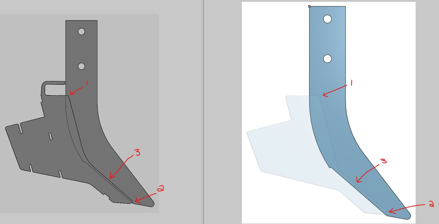
What's difficult to do is mate the rounded corners of the side plate to the flat face of the blank. This is a very common case for my line of design work. The side plates contact the blank face at the rounded corners labelled 1 & 2. I was able to replicate this but not correctly by using the vertex at the beginning of the radius and use a tangent mate to attach it to the face. When I used the tangent mate and clicked the arc of the radius and the face of the blank the side plate became parallel to the blank. This was not the desired result when I tried the vertex of the radius and the face.
The side plates are actually flared a little bit as you can see in the images below labelled Gap. Typically I need to create a dimension for the offset at label 3. This is another problem I am having trying to replicate this in OS.
Also, when I am pulling parts from another part studio into an assembly, I need to mirror the parts in the assembly so the BOM will be accurate. How do you create a mirror in OS Assemblies? As you can see in SW there are two side plates but only one in OS.
Can anyone help me replicate my SW results in OS? If I were to switch to OS and this situation was not do-able, I would not be ablet to migrate over to OS.
Grey parts created in SolidWorks--Blue Parts created in Onshape (Side View)
Grey parts created in SolidWorks--Blue Parts created in Onshape (Front View)

https://cad.onshape.com/documents/79f6f2d9bce0c2e9d083f0bf/w/3c1abd814c3db4d0b27e2703/e/814f95e15860a1c1d226af75
Thanks,
Logan
What's difficult to do is mate the rounded corners of the side plate to the flat face of the blank. This is a very common case for my line of design work. The side plates contact the blank face at the rounded corners labelled 1 & 2. I was able to replicate this but not correctly by using the vertex at the beginning of the radius and use a tangent mate to attach it to the face. When I used the tangent mate and clicked the arc of the radius and the face of the blank the side plate became parallel to the blank. This was not the desired result when I tried the vertex of the radius and the face.
The side plates are actually flared a little bit as you can see in the images below labelled Gap. Typically I need to create a dimension for the offset at label 3. This is another problem I am having trying to replicate this in OS.
Also, when I am pulling parts from another part studio into an assembly, I need to mirror the parts in the assembly so the BOM will be accurate. How do you create a mirror in OS Assemblies? As you can see in SW there are two side plates but only one in OS.
Can anyone help me replicate my SW results in OS? If I were to switch to OS and this situation was not do-able, I would not be ablet to migrate over to OS.
Grey parts created in SolidWorks--Blue Parts created in Onshape (Side View)
Grey parts created in SolidWorks--Blue Parts created in Onshape (Front View)
https://cad.onshape.com/documents/79f6f2d9bce0c2e9d083f0bf/w/3c1abd814c3db4d0b27e2703/e/814f95e15860a1c1d226af75
Thanks,
Logan
Tagged:
0
Comments
Of course, one easy way to circumvent these issues is to design the parts in the correct location relative to each other. Not only does this make designing the parts easier since you can see and reference the other part while designing, it also greatly simplifies assembly since inserting parts into the default position and then grouping them together constrains them robustly and quickly.
FRC Design Mentor - Team 1306 BadgerBots
https://cad.onshape.com/documents/e7e991f1acd531d7bc109fe5/w/71dd27b43c18dacb286564ce/e/addac5bd676745ad6795582f
One thing you might try is creating a sketch with key geometry/offsets and adding that to your assembly so that you can define the correct angles between your parts. How do you define the angle of the "flare"? What axis is that angle rotated around?
Also - you can easily add multiples of any part into an assembly, by clicking on it more than once in the insert dialog. You can also click on a part in the assembly parts list and copy/paste to create another instance of it.
With regards to Assembly mirror not being a thing. I can insert more instances but then recreating those tricky tangent mates becomes double the hassle and really a horrible experience with OS. I wish the mates could utilize OS creative methods but also utilize the tried and true versions that most CAD systems use to help the transition.
I tried a fastened mate between the two sketches and applied a rotation angle about the Z axis of 5 degrees. It flared one side as expected but made the other side flat against the middle shank. I have not had any luck getting the 1/8" offset to work. Everything I do flattens the side plate against the blank.
I looked and could not find a plane reference in the Assembly. Are planes not important for Assemblies? Rhetorical question, yes of course they are. Why aren't they here, Onshape?
I have about 30 different side plates that we use for different applications on a couple of shank designs. I thought the best way to organize the parts were to create a part studio with all the different side plates in it as flat patterns that we buy from a laser shop and then for each knife design have it be a separate part studio that I can import the side plates into the assembly and place them where I need them (similar to how I manage assemblies in SW).
@NeilCooke, can you assist or point me towards someone that can work with me directly to try and find a solution to this issue?
Also, if you have 30 different side plate designs, splitting them into separate documents will allow you to more easily have version and revision control over them independently.
So, if you have a document with parts A, B, and C in separate part studios. You can create version 1 of that document. Then, insert part A-v1 into an assembly. You could then go back and modify part B and create version 2 of the document. Over in your assembly, part A will show that there's an update available because the document was updated.
However, once you release a part and create revision, then you can tell your assembly to only flag you if Part A is updated to a new revision level.
This is one area where onshape is a little confusing, but can be powerful once you get a hang of it.
Summary: "Versions" are snapshots of an entire document at a specific instance in time. "Revisions" apply to released parts and are tied to a specific part number.