Welcome to the Onshape forum! Ask questions and join in the discussions about everything Onshape.
First time visiting? Here are some places to start:- Looking for a certain topic? Check out the categories filter or use Search (upper right).
- Need support? Ask a question to our Community Support category.
- Please submit support tickets for bugs but you can request improvements in the Product Feedback category.
- Be respectful, on topic and if you see a problem, Flag it.
If you would like to contact our Community Manager personally, feel free to send a private message or an email.
Designing mechanisms in 2D in Onshape
 lougallo
Member, Moderator, Onshape Employees, Developers, csevp, pcbaevp Posts: 2,016
Designing mechanisms is necessary in many mechanical design challenges and sometimes the easiest way to do it is to use 2D blocks to test out and tweak lengths and interfaces in order to tune the mechanism. In Onshape I was refining a robot gripper and tried out a few approaches to get it right before using the layout as a base for my part creation.
FIRST...
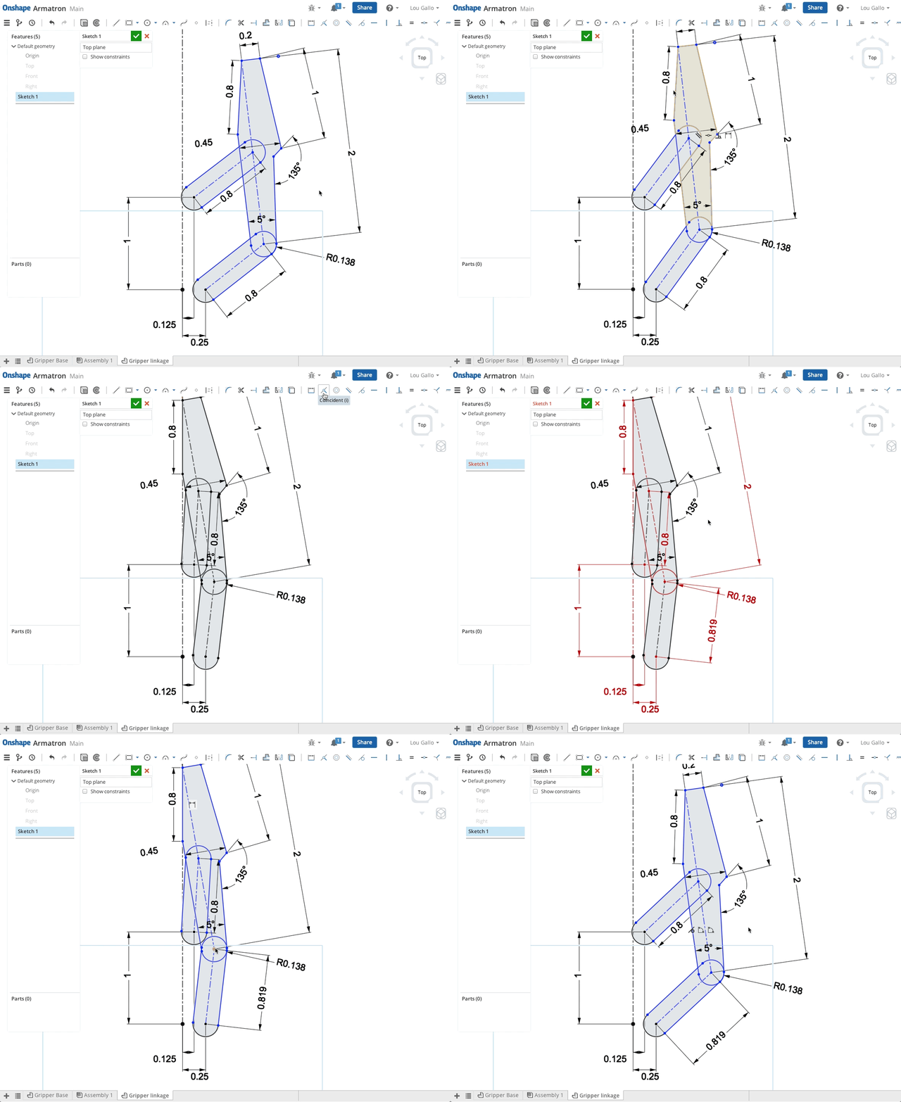
I wanted to make sure that the gripper interface would touch parallel to the center of the gripper so the entire interface would be engaged at full closure. Not knowing the exact size of the linkages to make this happen (and avoid having to do any hand calcs) I let the CAD tool do it for me.

FIRST...
- Place 3 construction lines and connected them in relation to one another. (avoiding relations like vertical, horizontal, etc). I only added what was needed to restrain the size of the construction lines.
- Add sketches to define the shapes of the mechanism components (links in my case) only adding relationships to the main construction line that defined the link length.
- Move the mechanism to visualize the motion
- Tweak the lengths to fit the motion you want.
I wanted to make sure that the gripper interface would touch parallel to the center of the gripper so the entire interface would be engaged at full closure. Not knowing the exact size of the linkages to make this happen (and avoid having to do any hand calcs) I let the CAD tool do it for me.
- Remove the length of my bottom linkage (originally set to 0.8")
- Add a coincident relation to the gripper face sketch and the centerline of the gripper
- Add a dimension to the bottom linkage, which will over-define the sketch (which is fine)
- Remove the relationship

Lou Gallo / PD/UX - Support - Community / Onshape, Inc.
Tagged:
1
Comments
I would have a conversion with Joe and Andy about this. My last job was to solve this problem and we came up with a pretty unique way of handling 2D mech design - but I'm under post NDA from Dassault not to discuss it.
- What I can say is that over the years, the practice with many designers doing mechanism design in SW is to
create a layout sketch of the beginning and end positions (or intermediate positions also) and apply sketch constrains to completely solve the path/position. (see below example.)
This works pretty well but it is sometimes hard to visualize and in addition dynamically move and also have a definitive solution.
- One thing that OS really needs and would go a long way toward mech design is to be able to make OS dimension driven/driving; I'm not sure OS has this capability or I have not found it yet?
Mark
LearnOnshape facebook group
My 2 cents
Mark
I've never really mastered using the sketch blocks in SW but tend to added a bit of detail on the sketch to get clearance restraints/boundarys. The key is to keep these sketches simple, they very powerful and the key to most of the products I design.
When I have done cams in the past, it has been with basic sketches and manually moving bit of the sketches to visualise the operation, these mess with your head and it's good to know there's not even a way to do it in SW because I have looked with no success.
I have found in OS I can add mate connectors to my sketches which blow through to the assembly this great because I can drive my assemblies to positions off the layout sketches. Is there any plans to be able to sketch in an assembly? (maybe you don't need too, it might be better to retain all sketches in the part studio), I think I'd be fine with out assembly sketching but I would like to see the driving sketch and be able to drive sketch dimensions from the assembly.
Bruce
Twitter: @onshapetricks & @babart1977