Welcome to the Onshape forum! Ask questions and join in the discussions about everything Onshape.
First time visiting? Here are some places to start:- Looking for a certain topic? Check out the categories filter or use Search (upper right).
- Need support? Ask a question to our Community Support category.
- Please submit support tickets for bugs but you can request improvements in the Product Feedback category.
- Be respectful, on topic and if you see a problem, Flag it.
If you would like to contact our Community Manager personally, feel free to send a private message or an email.
How to create this 3D sketch in Onshape?
 mike_hölscher
Member Posts: 110 ✭✭✭✭
Hello,
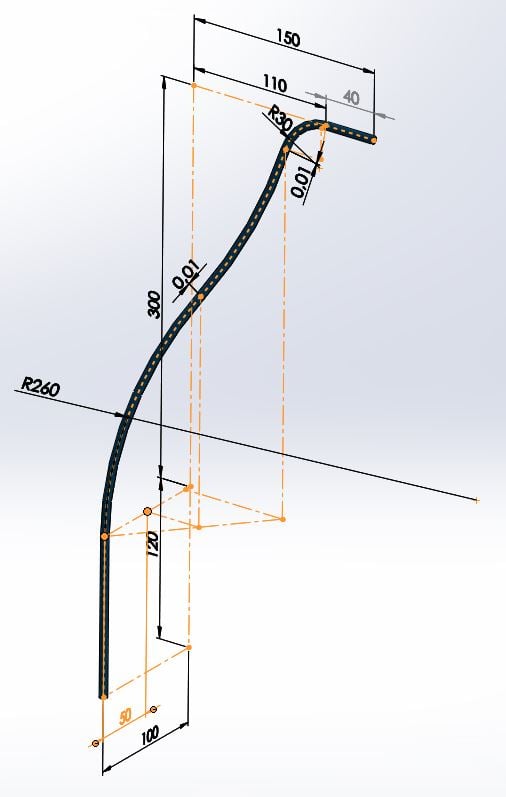
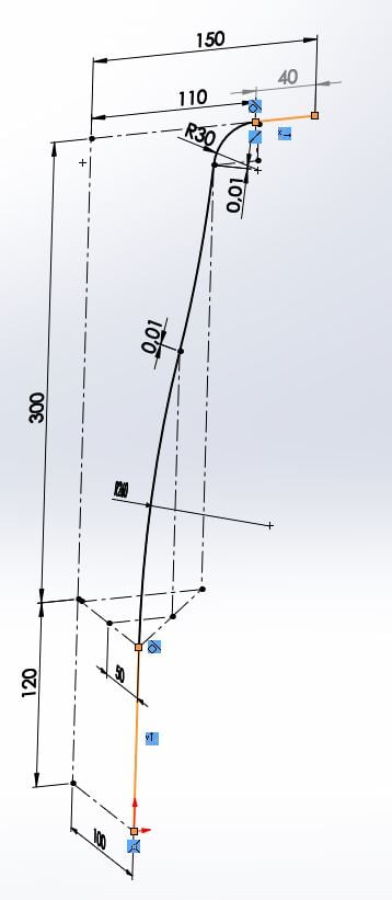
We have got this 3D bent spring wire in our product. In SW this already was some hassle to set up using 3D Sketch because it would suddenly give an overdefined sketch for no reason when adding tangent relations between multple arcs in a 3D sketch. However, it was fixed by adding small straight pieces (0,01mm, as you will see in the pictures) in between the arcs and it all worked fine.
That is all history. Now I would like to remodel this wire in Onshape. There is no 3D sketch, and a spline is not what we want. When trying to make multiple planes to create this shape, the problem arises that the location and orientation of the planes depend on dimensions cannot be defined yet. In the right picture below, the orange start and end lines (40 and 120mm) can be defined using 2 planes. The 3 arcs in between can be placed on 2 other planes (the R30 on one plane, and the two large radii on another plane), but where these planes should be in space totally depends on all of the chosen dimensions of the arcs.


Does someone know how to create this shape in Onshape right now?
We have got this 3D bent spring wire in our product. In SW this already was some hassle to set up using 3D Sketch because it would suddenly give an overdefined sketch for no reason when adding tangent relations between multple arcs in a 3D sketch. However, it was fixed by adding small straight pieces (0,01mm, as you will see in the pictures) in between the arcs and it all worked fine.
That is all history. Now I would like to remodel this wire in Onshape. There is no 3D sketch, and a spline is not what we want. When trying to make multiple planes to create this shape, the problem arises that the location and orientation of the planes depend on dimensions cannot be defined yet. In the right picture below, the orange start and end lines (40 and 120mm) can be defined using 2 planes. The 3 arcs in between can be placed on 2 other planes (the R30 on one plane, and the two large radii on another plane), but where these planes should be in space totally depends on all of the chosen dimensions of the arcs.


Does someone know how to create this shape in Onshape right now?
0
Answers
https://cad.onshape.com/documents/57acdfaae4b005c413ed9b6f/w/3fd585a46d3af1b3ba413c53/e/8a2843094b5b0c5823147f56
@mike_hölscher shows an example where he may not have or know the dimensions of what would be the Projected Sketches to produce that result.
I understand the 3D wire shape is hard to judge from two pictures, but mahir actually came pretty close in his example. Thanks for that!
I did not think of the projected curve method yet, so thanks! Unfortunately is does not do what I want exactly. I will try to explain using the pictures below where I added 4 planes on top of the SW 3D Sketch to clarify:
Actually, the shape could be on two planes, Plane1 and Plane2. Note that Plane2 is not parallel to Plane4, is has a slight angle. As you can see in the first post, no plane angles are defined by me. The plane angles depend on all of the dimensions in the 3D Sketch, so dimensions on multiple planes together. In the 3D Sketch, Plane1 and Plane2 are the planes where the radii are defined. However, the endpoint distances are all dimensioned from the orthogonal planes, Plane3 and Plane4. This is because of the application and production method. Dimensioning the radii from the Plane3 and Plane4 (like in mahir's example) gives a different radius on Plane1, not giving the wanted result. Actually, projecting two circular radii using Projected Curve gives an ellipse, right?
I guess I have to do some trial and error work to get as close to the original curve as possible, until Onshape 3D Sketch comes out.
That said, the advice here is sound and you absolutely will be able to make this part using the functionality available today
For now, if you need specific (and different) radii, you'll need to piecemeal the different sections together, putting the radii on their own planes/sketches. You can combine the sketch segments after the fact using the Composite Curve function.
You are saying I should be able to this using Projected Curve? I do not think it is possible to get a projected curve with a specific radius based on two sketches with other radii. Please prove me wrong.
As I expected, two radii make an ellipse:
https://cad.onshape.com/documents/6a57695ba486feeed5ec0256/w/141c1913c4d51db353742abf/e/2d3046501cae66af858beb18
Thanks @mahir
I had to lookup 'piecemeal'
To do this today manually, requires multiple planes and sketches.
Here is a plan;
1) As a pro-user, please please please submit your desire for a 3D sketch
2) I will look at better workflows - potentially automating aspects of this using custom features
1. The 30mm radius "points" to the endpoint of the 120mm line segment. This is assumed to be true based on the planar and tangent nature of the curve segments.
2. The 50mm dimension where the two large radii meet is not super important. This instead ends up being about 38mm and is driven by other geometry. I can place the point at exactly 50mm, but then you'll have to give up on some other constraint elsewhere in order to avoid being over constrained.
https://cad.onshape.com/documents/57acdfaae4b005c413ed9b6f/w/3fd585a46d3af1b3ba413c53/e/8a2843094b5b0c5823147f56
Top
Front Right
1. Voting up the 3D Sketching in Improvement Requests was like the first thing I did when first visiting this forum
2. Looking forward to your workflow and possible FeatureScript!
Wow! Thanks @mahir for putting in so much time and effort in this challange!
Unfortunately, your assumptions are not valid. These assumptions do make it easier to draw the shape in Onshape which is very close to what we have in SW, like you have done. The 50mm IS important and changes the angle of Plane2, and with it, it slightly changes the angle of Plane3, and together also change where the R30 is pointing. I will be looking closely at a copy of your part to see what I can do with it. Thanks!
@konstantin_shiriazdanov . I am not completely following you. Make separate sketches of the curves and bring them together in an assembly? This does sound interesting... EDIT: Just tried inserting sketches into an assembly. Did not know this is possible! Might just be a solution because using the mates you can allow the sketches some freedom to move and possible also have these two curves tangentially connect. Not sure yet, but very interesting...
How easy would a 3D sketcher in Onshape be in this case
I'm all for having 3D sketching capabilities built into OS, but perhaps this is a case of misplaced design priorities? Case in point, is the form/fit/function of this spring really driven in any appreciable capacity by the locations of these inflection points? If so, I stand corrected, but my engineer senses are leaning the other way.
Keep in mind, I'd rather have a 3D sketch.
@jon_sorrells Wow, really creative! Smart to put everything in one sketch to put in relations and transform and project. Too bad it looks like the result of projecting ellipses are no arcs/radii.
@billy2 Yeah, I also like this spline. But I really need to dimension arcs for the required result.
I always appreciate a puzzle. If I think of something I'll let you know. I have a feeling it will require some trig and variables.
One way I can think of to recreate springs generated by the SW 3D sketch is to increment the angle for the plane containing the 30mm radius until the lower inflection point is actually at 50mm. You'd have to do this for each existing configuration. But once it's done, it's done. After that, any future new configurations can either ignore that 50mm dimension, or you can run the iteration process again. It's not a pretty solution, but it's feasible. In my example below I'm using a distance measurement as a sensor to see if the prescribed angle (~19.96deg) gives the desired 50mm dimension.
https://cad.onshape.com/documents/57acdfaae4b005c413ed9b6f/w/3fd585a46d3af1b3ba413c53/e/8a2843094b5b0c5823147f56
But lets be honest, 3D Sketching should really be in a CAD program calling itself 'Modern'. This is not something like Feature Tree Folders that you can have different opinions and views on. 3D Sketching is just something designing needs. So @NeilCooke , tell @philip_thomas, to get his noodles on
Here is my contribution.
Perhaps not so much in this particular case, but in general, there are some common challenges.
Yes we know that users want 3D sketching and it's coming.
In the meantime, there are some basic things that would help.
A typical use case is a 'space frame' - lots of straight lines in different sketches and no way to fillet between the two sketches . . .
UNTIL NOW!
This custom feature takes any two lines (from different sketches) and will make the fillet between them.
It will optionally also recreate the (shortened) lines and optionally the plane used (may be useful later).
I hope this helps
https://cad.onshape.com/documents/f2142f9b0b8676a357bed10e/w/5bfb4561275b308a9eb79a04/e/2a67ba030b8802c069148086
I will play around with it.
I have added this to my FS website ( http://featurescripts.bubbleapps.io )
Is that ok?
IR for AS/NZS 1100
My favorites (just in case they are not in your list) are;
Enhanced Planes
Ray Tracing
Extend surface
Extend Point
Enhanced Measure
3D xyz
Sketch wrapper
Thread Creator
Fix PCB
Belt
Here is a feature (that uses yours) that lets you use lines as input, and select more than two lines: https://cad.onshape.com/documents/5d235ff0a55e76d384b9e1a4
IR for AS/NZS 1100