Welcome to the Onshape forum! Ask questions and join in the discussions about everything Onshape.
First time visiting? Here are some places to start:- Looking for a certain topic? Check out the categories filter or use Search (upper right).
- Need support? Ask a question to our Community Support category.
- Please submit support tickets for bugs but you can request improvements in the Product Feedback category.
- Be respectful, on topic and if you see a problem, Flag it.
If you would like to contact our Community Manager personally, feel free to send a private message or an email.
"Same same, but different" or WTF with arks
 evgenii_fyodorov
Member Posts: 9 ✭
evgenii_fyodorov
Member Posts: 9 ✭
So, I want to put an arc in my sketch. I have a center point, I have a point where I want to start this ark and where I want to end it. So I use the center point arc tool and watch how half of my sketch get's lid in red, like so:
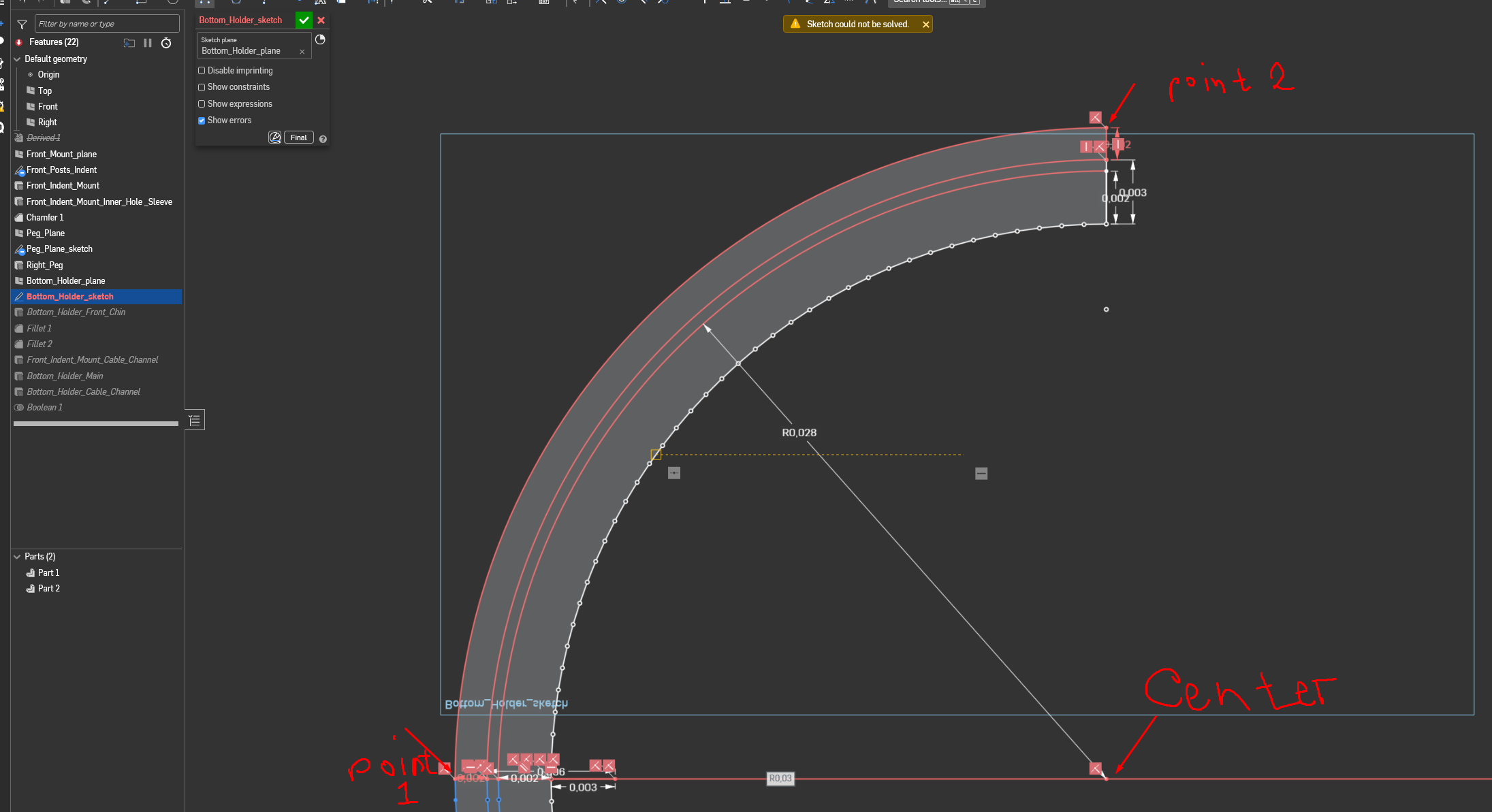
But when I do literally the same thing, but instead of ending ark in one of those two points, I continue the arc just a little bit further - everything is ok, sketch resolving correctly:
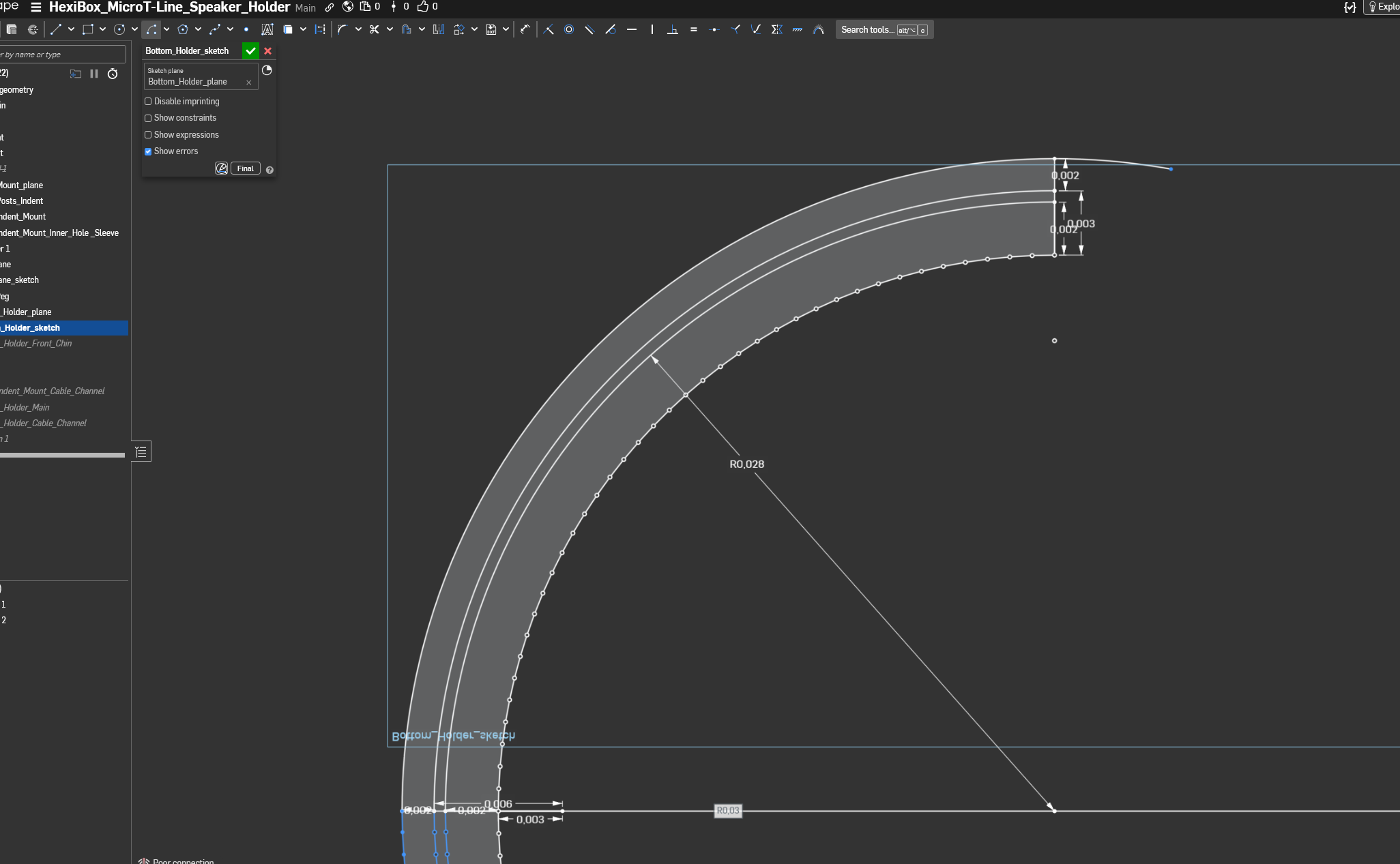
And that would be fine except that now I'm getting a loose end in my sketch. Which makes me a bit annoyed.
As far as I can see, it does not matter which direction the arc is made - the result is always the same. It precisely passes through both point 1 and point 2, but everything resolves correctly only when I get it past the ending point.
I acknowledge that I did not use any courses to teach myself CAD. I prefer just to dive right into making something. And when I eventually get stuck on something that I don't know how to resolve or how to do, the trial-and-error method (with a bit of heavy swearing) usually does the trick. But this time, I can't explain what's happening to Google well enough to get to the answer.
Thanks in advance for wasting time on my problems)
https://cad.onshape.com/documents/212f3144157fe77975f92f73/w/cf2d9021a4958718c308cf82/e/2f9467bf56600dd6362b8911?renderMode=0&uiState=697df61170507c976b079296
Comments
That is strange. I can't comment on why it's red. But since it works if you go past the point, what if you just use the Trim tool to trim off the loose end?
If that doesn't work then probably something is not lining up the way that it seems.
Unemployed Onshaper - operating on European time. More of me here ➤ https://linktr.ee/Liam.G
I'd suggest experimenting with different 'Workspace Units' - yours are currently set to meters which can't help with accuracy.
Unemployed Onshaper - operating on European time. More of me here ➤ https://linktr.ee/Liam.G
Yep, Trim does not work.
Initially, I set workspace units to be represented by the SI standard, like in physics. So, given that a millimeter is 0.001 of a meter, it is not surprising that when I switched to millimeters, the result is the same. But, I must admit that writing "0,00" before all my values is kinda tedious, at least at the start.
Millimetres are also SI units. It's not surprising that your sketch is having difficulties solving - why are there so many short, unconstrained lines? The general rule of thumb is to keep sketches simple with no more than 20 entities or so.
Can I forward your comment to every undergrad engineering CAD professor? There's this tendency to show students final drawing views of fully finished products with hundreds or thousands of lines and dimensions and conflate that with master sketch modeling practices. It's probably the thing I see done most often that slows down new hires fresh out of school and some people carry that practice into industry for way longer than they should.
Derek Van Allen | Engineering Consultant | MeddlerThe whole thing I'm making is based on the geometry of an outside model that I imported. At this point, I got everything that I needed from it, so I suppressed it.
I left those short lines unconstrained because I didn't see a more elegant way to do this, except to constrain every single small line separately.
As I said previously, I'm not a professional in this field. I'm making things for myself and learning while doing it. If there is a better way to get geometry from an imported model, I don't know it, so if you can point me in a general direction of a specific tool and/or method, I would much appreciate it. Otherwise, if I interpreted what you wrote correctly, I should go and divide my single sketch into 3 to 5 smaller ones and constrain every single short line, right?
I'm sorry that I'm bothering professionals with my silly questions.
Yes split it up into smaller sketches but absolutely don’t have small lines or try to constrain them. That imported part is tessellated for 3D printing so if you want a model that you can edit then you should approximate all those short lines with a single arc.
Ok, so I have a new project with a very similar problem.
As you said, I keep sketches simple with no more than 20 entities or so. At this point, I am not trying to copy any preexisting geometry from imported parts. There are no short unconstrained lines. Matter of fact, there are only 2 lines and three points. Points are projected from another sketch.
When I try to create an ark, I get this:
What am I doing wrong now?
https://cad.onshape.com/documents/69e7729efc7e85734969bb28/w/68aefed83c649b34e9d41bf0/e/2857a9717d932c5277e766f0?renderMode=0&uiState=6985101c2414e16ef38afc85
It's overconstrained - delete one of the 1.5 dims
For your main arc shape in your original question, you could have had the main sketch have a single arc, instead of 4 offset arcs. Then use thin extrude to make your shape. Then use thicken (new) to do the additional ribbing, and move face of those thickens. Then union everything at the end. Much simpler and easier.
Actually, scratch all that. Looking again, sweep is probably the way to build your part. A single line for the path, and another sketch of the cross section.
How can center arc work with 3 points from a geometry standpoint? (if the 3 points are constrained). The center point and the first point will define the radius. The third point if it was arbitrarily placed into space, will not be on the same radius, and the arc won't touch it.
Here is your main shape in 4 features, using sweep.
Thanks, that info was quite useful for me.
I learned the usefulness of things outside of sketch and basic extrude only yesterday, when I tried to make a knurling. There is still a lot to discover there.
Although I think I will leave my original part as it is right now, because, as I learned earlier today, it is easier to remake something from scratch than change something that already exists (made a dial with knurling and stuff, and then realized that I used the desired diameter as radius).
So, the answer to the original question is that I need to learn more.
Thanks to everyone.