Welcome to the Onshape forum! Ask questions and join in the discussions about everything Onshape.
First time visiting? Here are some places to start:- Looking for a certain topic? Check out the categories filter or use Search (upper right).
- Need support? Ask a question to our Community Support category.
- Please submit support tickets for bugs but you can request improvements in the Product Feedback category.
- Be respectful, on topic and if you see a problem, Flag it.
If you would like to contact our Community Manager personally, feel free to send a private message or an email.
Reverse Engineering with OS
 billy2
Member, OS Professional, Mentor, Developers, User Group Leader Posts: 2,119 PRO
How do you design a cover for something you have no prints, drawings or models?
I don't normally post stuff like this but the results were much better than I expected I thought others might benefit from this simple technique.
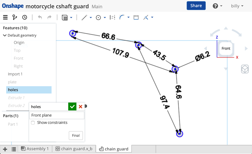
The secret sauce was to use OS to triangulate these holes and find their locations accurately. I was really surprised at how accurate the hole locations match.
original note
Simple Technique
So, I wanted to design a new counter shaft cover but I have no idea where these holes are located:
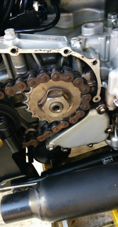
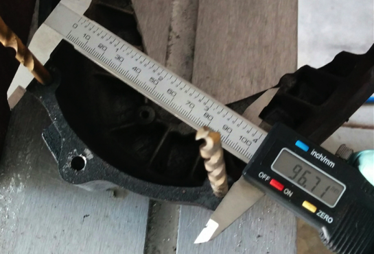
Working with the old cover, I placed drill bits in the existing holes and zero'd out my $9 harbor freight calibers:
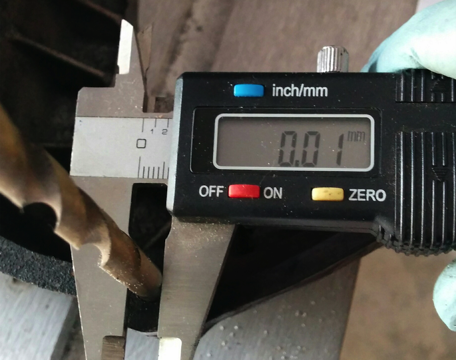
Because I zero'd the calipers out on a drill bit diameter, the number shown is the center line distance between the holes:
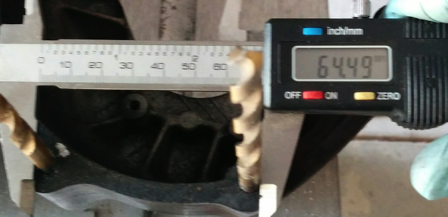
You have to measure each hole relative to each other:
Now for the OS stuff
I made a sketch and created holes with the dimensions I measured:
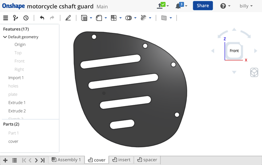
Then I added the new cover shape:
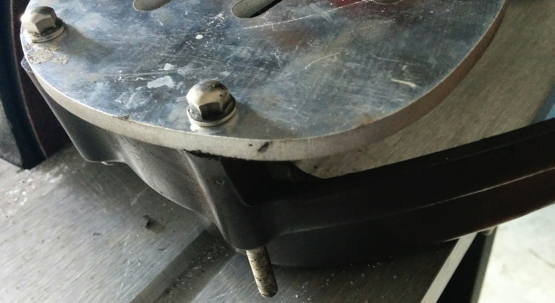
This is the new waterjet part setting on top of the old cover with the bolts running through both. Now the hole clearance for the bolt is really tight, yet everything fits. I was figuring on opening up the holes in the the new plate to 7mm to allow for mis-alignment of the holes, but no need for that!
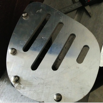
Bolts fitting through new plate and old cover:
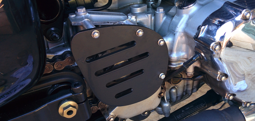
Anyway, $9 worth of CMM tools and I'm done:
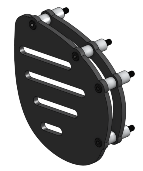
Round II Stylized
Ok so I'm not done, I'm cutting more waterjet parts tomorrow and came up with these stylized changes.
-added bolt boss accents
-c'bored bolt heads
-added sub-cover
I don't normally post stuff like this but the results were much better than I expected I thought others might benefit from this simple technique.
The secret sauce was to use OS to triangulate these holes and find their locations accurately. I was really surprised at how accurate the hole locations match.
original note
Simple Technique
So, I wanted to design a new counter shaft cover but I have no idea where these holes are located:

Working with the old cover, I placed drill bits in the existing holes and zero'd out my $9 harbor freight calibers:

Because I zero'd the calipers out on a drill bit diameter, the number shown is the center line distance between the holes:

You have to measure each hole relative to each other:

Now for the OS stuff
I made a sketch and created holes with the dimensions I measured:

Then I added the new cover shape:

This is the new waterjet part setting on top of the old cover with the bolts running through both. Now the hole clearance for the bolt is really tight, yet everything fits. I was figuring on opening up the holes in the the new plate to 7mm to allow for mis-alignment of the holes, but no need for that!

Bolts fitting through new plate and old cover:

Anyway, $9 worth of CMM tools and I'm done:

Round II Stylized
Ok so I'm not done, I'm cutting more waterjet parts tomorrow and came up with these stylized changes.
-added bolt boss accents
-c'bored bolt heads
-added sub-cover

2
Comments
I'd like a quick dxf export, into a tab, possibly even linked for geo changes and a direct email to supplier for this kind of work.
Bruce
Twitter: @onshapetricks & @babart1977
@babart77 there is no DXF export yet that I am aware of. I export a parasolid and import into SW and then DXF. However word on the street is that the drawing package is almost there and soon we can do the DXF thingy....
LearnOnshape facebook group
Maybe I'll take a stance and send him step files and improve the world one supplier at a time.
@LouGallo Does this mean you guys are considering support for documenting the models based on ASME Y14.41... Model based definition, model based design, etc...? That would be fantastic. I share the angst about 2D drawings - a necessary evil but not nearly as efficient as it could be.
Joe